
Installation & Assembly

READ& SAVE
THESE INSTRUCTIONS
INSTALL
ATION OPERATION
INSTRUCTIONS
IOOLS &
MATERIALS REQUIRED
O
Blarle screg ilrir e
o
Adjustablc
rr
re::::,
o
Step l:,1cr:
a \\
rre cutter
a
\\
lilng supplies
as required by
electrical code
CAUTION
:before
assembling
your lighting fixture, refer to the
section tjtled
ELECTRICAL COn-NECTIONS .lf
you
feel
you
do not
have
electrical
u'iring experience .reler to
a do-it
)
ourself
t'iring handbook Or
har e
I
our i:rture installed by a
qualilied
licensed electriclan.
GENERAL
1.To ensure
the
success
olthe installatrLrn. be
sure
to readlhese
insrruction rer-iew the diagrams thoroughl-v before beginning
L
\ll
electrical
connection must be in accordance
*,ith
local
codes. Ordinances,or
the Nationai Electrical Code. Ifyou
are un-familiar
with methods of installing electrical wiring.
secure
the
services
ofa
qualified
licensed electrician.
3.
These fixtures are
j
nten ded to be mounted to a4"
*2
1 lR" deep
metal octagon outlel
box. the
box
must directl1, supported b-v
rhc
DLriJll
q
1[ructurts.
'1.Belore starting the installation .disconnect
the power
by turning
offthe circuit breaker or by removing
the fuse
at the
fuse
box.
turnrng
the pou,er
offusing
the light
s*.itch
is not
sufficient to
pre\
ent electrical shock.
NOTE:
The important saleguards
and instructions
appearing in
this manual are not meant to co\ er a11
possible
conditions
and
situations that may occur
.lt
must be understood that common
sense, caution. and care are lactory which
cannot be built
into
any
product
.These factories must be supplied by the
persons
caring for and operating the firture.
UNPACKTHE FIXTURE
Check the conlents ofthe
box,
You should receive
r,\lountrng hard
s
arc
package
o Lamp holder asse mbLl
is
)
. Mounting bracket
r
Shade(s)-not
provided
on all models
o
Shade attachment screws(3 for each shade)not
provided
on
al1 models
PREP ARE THE FIXTURE
NOTE: FIRST TURN
OFF ELECTRICITY
l.lfyou are replacin an existing fixture
,
disconnect and remove
the
old
fixture. Expose
the supply wiring from the outlet box.
2.Some fixtures
are
provrded
with a threaded nipple or machine
screws for attaching the fixture to the mounting bracket, Ifyour
frxture is supplied with a threaded nipple, screw the nipple 3
complete turns into the mounting
bracket and
lock into place
with a hexagon lock. lf
your
fixture is
supplied
with machine
screws,
thread
the
machine
screws
into
the opposite side of
the mounting
bracket
from the green ground
screw. Lock the
machine scre\\'s
into
place s.ith
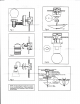
lock nUts.EXCEPTION
:Ceiling
mounted firture with
kevhole
slots should har e machine
screws
entering
mounting bracket liom sarne srde as
green grounding
scre\\,(see
Fig.2.A)
3.Fasten
the mounting bracket to the outlet box using the two
screws
supplied
s
ith the outler bo\
.Ill our
fixture is
supplied with a
channei shape mounting
bracket
*
ith keyhole slots for
attachment
to the
mounting
surface(See
Fig 3), it will be necessary to mark the
location cf the kevhole slots on the mounting surface and dri11 holes
for
tastener:inot prolided)Use fasteners
suitable
tbr the
mountins
suriace.the narro\\-end ofthe keyhole slot should face up.
4.Attach
groundine s'ire(green
or bare copper)from the suppiv circuit
to
the
mounting bracket
ri
lth the
green grounding
attachment
scre\\'
pror
ided.
Some models have a
grounding
wire attached to the
fixture. For models that employ a
green
or bare copper
grounding
Wire . it will be necessary to connect the
green
or bare
grounding
\\'ire to the
grounding
conductor of the supply circuit,Attach
ail
grounding
conductors to the mounting bracket with the
green
grounCing
attachment
screw.
5.N'lake
eiectncal connections-SEE BELO\\-.
ELECTRICAL
CONNECIIONS
To mak.' electrical connections:
Conncct
the
u
hite u ires from the fixture to lhe
white
wire oi
the supp11-circuit .Connect the black
rvires
.lrom the fixture to
The
black
wire ofthe supply crrcuia. Connect
the
green
or bare
copper colored
wire to the
grounding
conductor ofthe
suppl1-'
Circuit
,Ifyour
fixture is supplied with an SPT Cord connect
rhe half
of
the
SPT
Cord that is ribbed surface to the white wire
ofthe supply
circuit. Connect the smooth hailofthe wire(the half
with mark-connectors suitable
lor the size type, and number
of
conductors
.No loose stands or
ioose r.l'ires
should be
present.
Secure
u,ire
cLrnnectors
g,ith
U.L Irsted electricai tape)
FINAL ASSEMBLY
1.
Spread
the electrical splices so
that the
black
u ires are
side
ofthe outlet
box and
the
white wires are on the other side.
2. Place fixture against
mounting
surfac e
allos'ing the threaded
nippie
or machine scre\\ s
to pass
through the cover
plate.
Secure
with mountingNut or acorn nuts .For fixture with
channel shape
mounting bracket
,place
the cover
plate
over
rhe chanr.iel ard secure with screu's
provided.
3 .Ifapplicable
,Place
candle cover(s)over lamp hoLders
before
installing
bulbs .Install the
light
bulbs(not
provided)
CAUTION
:Refer to there lamping label located near the lamp
holder
for recommended
maximum
wattage-do not
exceed
recommended wattage
4.Ifapplicable,attach
shades
to
fixture
,Some
shades require the
use of shade attachment screws,Do not over tighten these
screws-too much
pressure
could cause
glass
bleakage. See
Fig
4 for replacement
offabric
spacer, not supplied on all models.
5. outdoor
rvall
fixture must be caulked
with
suitable
RTV or
silicone compound
around the to
pan
sides ofthe cover
plate
to
reduce the chance ofwater
intruding rnto the silicone area.
Lea.re the bottom clear to allow moisture a
means of escape.
6.Restore electricity
and
check
the
operation
ofyour new
lighting
fixture