
Installation Instructions

CAUTION RISK OF FIRE-
This product must be installed in accordance with
the applicable installation code by a person familiar
with the construction and operation of the product
and the hazards involved.
Use minimum 90°c supply conductors.
Outdoor
1A
13
GP I :ENERAL RODUCT NFORMATION
These fixtures are intended to be installed utilizing compliant junctionNEC
boxes.
This product is safety listed for wet locations.
Incandescent lamps may be dimmed with a standard incandescent dimmer.
LED LEDlamps may be dimmed with a dimmer. Consult lamp manufacturer for
additional information.
This instruction shows a typical installation.
1
2
3
4
5
6
7
8
9
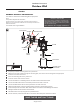
LAMP
10
FIXTURE
SCREW
MOUNTING
PLATE
3
4
9
JUNCTION BOX
GLASS SHADE
FIXTURE
BASE
BOTTOM COVER
8
COVER SCREWS
11
12
FIXTURE
5
ANCHOR
ANCHOR SCREW
7
10
11
12
13
Outdoor Wall
Temporarily install the mounting plate to the junction box.
Mark the anchor hole locations through the mounting plate, then remove the mounting plate.Drill appropriate
sized holes and install the anchors.
Secure the mounting plate to the junction box.
Screw the anchor screws into the anchors.
Connect the fixture to a suitable ground in accordance with local electrical codes.
Connect the white fixture wire to the neutral power line wire with a wire nut.
Connect the black fixture wire to the hot power line wire with a wire nut.
Mount the fixture base onto the mounting plate and secure it with the fixture screws.
Screw the lamps into the sockets. Refer to the label on the socket for Max Wattage Information.
Slide glass shade into the fixture from the bottom.
Install the bottom cover by using the four provided screws.
For wet locations, caulk around the base of the fixture with waterproof construction sealant.
All rights reserved.
Installation Instructions
SAVETHESE INSTRUCTIONS!