For all your newfangled gadgetry. Desk NOTE: THIS INSTRUCTION BOOKLET CONTAINS IMPORTANT SAFETY INFORMATION. PLEASE READ AND KEEP FOR FUTURE REFERENCE.
Table of Contents Part Identification Assembly Tools Required 2-3 Hardware Identification No. 2 Phillips Screwdriver Tip Shown Actual Size 4 Assembly Steps 5-22 Hammer Français 23-25 Not actual size Español 26-28 Electric drill with 1/4" bit (ONLY in indicated step) Safety 29-30 Warranty 31 Now you know our ABCs. Part Identification å While not all parts are labeled, some of the parts will have a label or an inked letter on the edge to help distinguish similar parts from each other.
Part Identification G D2 J D2 E2 F H2 A K I C2 L D109 M D107 D707 B D108 L T N M D78 D14 D716 D15 O Page 3
Hardware Identification å Screws are shown actual size. You may receive extra hardware with your unit.
Step 1 å Assemble your unit on a carpeted floor or on the empty carton to avoid scratching your unit or the floor. å To begin assembly, push twenty-one SAUDER TWIST-LOCK® FASTENER (10F) into the large holes in the RIGHT END (A), LEFT END (B), UPRIGHTS (C2, D2, and E2), MODESTY PANEL (H2), SHELF (I), and BRACES (L). Do not tighten the TWIST-LOCK® FASTENERS in this step.
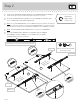
Step 2 å Separate the EXTENSION SLIDES (35MC) from the EXTENSION RAILS (35MA) as shown in the upper diagram below. Be prepared, the parts are greasy. å Fasten the EXTENSION RAILS (35MA) to the LEFT END (B) and UPRIGHT (C2). Use four GOLD 5/16" FLAT HEAD SCREWS (3S). å NOTE: For each EXTENSION RAIL, turn a SCREW into the hole shown in the enlarged diagram. Then, slide the inner cartridge of the EXTENSION RAIL out to find the other hole that lines up with the hole in the END and UPRIGHT.
Step 3 å Fasten the UPRIGHTS (D2 and E2) to the HUTCH TOP (G). Tighten three TWIST-LOCK® FASTENERS. How to use the SAUDER TWIST-LOCK® FASTENER 1. Insert the dowel end of the FASTENER into the hole of the adjoining part. NOTE: The dowel end of the FASTENER must remain fully inserted in the hole of the adjoining part while locking the FASTENER. 2. Tighten the FASTENER with a Phillips screwdriver as tight as possible.
Step 4 å Finish drilling the six holes shown in the bottom surface of the TOP (F) using a 1/4" or 6.5mm drill bit. å Next, fasten the TOP (F) to the UPRIGHTS (D2 and E2). Use six BLACK 1-15/16" FLAT HEAD SCREWS (113S). Long rounded edge D2 ce urfa s d ishe n fi Un D2 F E2 Finish drilling the holes from the bottom surface. Use a 1/4" or 6.5mm drill bit. Then, use six BLACK 1-15/16" FLAT HEAD SCREWS (113S).
Step 5 å å Insert four METAL PINS (1R) into the BRACES (L). å NOTE: Be sure the METAL PINS insert into the holes in the LEFT END. Caution Fasten the BRACES (L) and SHELF (I) to the LEFT END (B). Tighten four TWIST-LOCK® FASTENERS. Do not stand the unit upright without the BACK fastened. The unit may collapse. Curved edge These holes must be here. Rounded edge B S ur f TW ace w it I FASST-LO h TEN CK® ERS 1R S ur f TW ace w it I FASST-LO h TEN CK® ERS These holes must be here.
Step 6 å Fasten the UPRIGHT (C2) to the BRACES (L) and SHELF (I). Tighten four TWIST-LOCK® FASTENERS. å NOTE: Be sure the METAL PINS in the BRACES insert into the UPRIGHT.
Step 7 å Fasten the SIDE BASES (M) to the LEFT END (B) and UPRIGHT (C2). Use four BROWN 1" FLAT HEAD SCREWS (12S).
Step 8 å å Carefully turn the assembly onto its front edges. å NOTE: Be sure the edges of the ANGLE BRACKETS are even with the edges of the END, UPRIGHT, and BRACE. å Fasten the BASE (N) to the LEFT END (B), UPRIGHT (C2), and BRACE (L). Use four BLACK 9/16" LARGE HEAD SCREWS (1S). Fasten four ANGLE BRACKETS (27G) to the LEFT END (B), UPRIGHT (C2), and BRACE (L). Use four BLACK 9/16" LARGE HEAD SCREWS (1S).
Step 9 å å å You will need someone’s help in this step. å NOTE: Be sure to support the MODESTY PANEL until it is fastened to the UPRIGHT (C2). å Fasten the MODESTY PANEL (H2) to the UPRIGHT (C2). Use two BLACK 1-15/16" FLAT HEAD SCREWS (113S). Pro Tip: Lift with your legs. And, you know, your arms. Carefully stand the assembly upright. Fasten the RIGHT END (A) to the MODESTY PANEL (H2). Tighten two TWIST-LOCK® FASTENERS.
Step 10 å å You will need someone’s help in this step. Fasten the TOP (F) to the ENDS (A and B), UPRIGHT (C2), and MODESTY PANEL (H2). Tighten eight TWIST-LOCK® FASTENERS.
Step 11 å Carefully turn your unit over onto its front edges. Lay the BACKS (J and K) over your unit. å å å Make equal margins along all four edges of the BACKS (J and K). å NOTE: Perforations have been provided for access through the BACK. Carefully cut out the holes needed. Caution Do not stand the unit upright without the BACK fastened. The unit may collapse. Fasten the BACKS (J and K) to your unit using the NAILS (1N). NOTE: Be sure to tap NAILS into the holes that line up over the UPRIGHT (D2).
Step 12 VIEW THE T-LOCK BOX VIDEO 1 2 The tabs should insert freely into the slots. Gently tilt the DRAWER SIDES side to side until the tabs slip into the slots. With the palm of your hand, tap the DRAWER BOTTOM down into the groove. Unfi sur nished fac e D716 D14 D14 D15 D15 O O Be sure the DRAWER BOTTOM inserts into the DRAWER FRONT groove. Groove å Insert the FILE DRAWER SIDES (D14 and D15) at an angle into the slot at each end of the FILE DRAWER FRONT (O).
Step 13 VIEW THE T-LOCK BOX VIDEO 1 2 The tabs should insert freely into the slots. Gently tilt the DRAWER SIDES side to side until the tabs slip into the slots. Unfi sur nished fac e With the palm of your hand, tap the DRAWER BOTTOM down into the groove. D707 D107 D107 D108 D108 T T Be sure the DRAWER BOTTOM inserts into the DRAWER FRONT groove. Groove Insert the DRAWER SIDES (D107 and D108) at an angle into the slot at each end of the DRAWER FRONT (T).
Step 14 å Insert the SLIDE CAMS (10A) into the large holes in the FILE DRAWER SIDES (D14 and D15). å Fasten the EXTENSION SLIDES (35MC) to the FILE DRAWER SIDES (D14 and D15). Use four GOLD 5/16" FLAT HEAD SCREWS (3S) through holes #1 and #3. å NOTE: The screw head in the CAM must be visible through the slotted hole in the SLIDE.
Step 15 å Fasten a PULL (168K) to the FILE DRAWER FRONT (O). Use a SILVER 3/4" MACHINE SCREW (20S). å Push the FILE GLIDES (4B) onto the FILE DRAWER SIDES (D14 and D15).
Step 16 å å Insert a SLIDE CAM (10A) into each DRAWER SIDE (D107 and D108). å NOTE: The screw head in the CAM must be visible through the slotted hole in the SLIDE. å Fasten a PULL (168K) to the DRAWER FRONT (T). Use a SILVER 5/8" MACHINE SCREW (15S). Fasten the DRAWER RIGHT (40CC) and DRAWER LEFT (40CD) to the DRAWER SIDES (D107 and D108). Use four GOLD 5/16" FLAT HEAD SCREWS (3S) through holes #1 and #4.
Step 17 å å Carefully stand your unit upright. å To insert the other drawer into your unit, tip the front of the drawer down and drop the rollers on the drawer behind the rollers on the unit. Lift the front of the drawer up and slide it into the unit. If you're doing this to help a friend, don't leave without a bite.
Step 18 å To make adjustments to the file drawer, loosen SCREW #3 (#4 in the top drawer) in the SLIDES a 1/4 turn, then turn the cam clockwise or counter-clockwise. Notice how the drawer raises or lowers as you turn the cam. By adjusting the drawers this way, it will help the DRAWER FRONTS line up better when closed. Tighten the SCREWS when finished with adjustments. å å NOTE: Please read the back pages of the instruction booklet for important safety information. This completes assembly.
Utilisez les instructions d’assemblage en français avec les schémas étape par étape du manuel d’instruction en anglais. Chaque étape en français correspond à la même étape en anglais. La pièce devant être attachée à l’élément est représentée en gris sur les schémas de chaque étape pour plus de précision. Comparer la “Liste de pièces” ci-dessous avec la “PART IDENTIFICATION” du manuel en anglais pour vous familiariser avec les pièces avant l’assemblage.
ÉTAPE 1 ÉTAPE 5 Ne pas serrer les FIXATIONS TWIST-LOCK® à cette étape. Attention: Ne pas relever l’élément dans sa position verticale avant d’avoir fixé l’ARRIÈRE. L’élément risque de s’effondrer. Assembler l'élément sur un sol à moquette ou sur le carton vide pour éviter d'endommager l'élément ou le sol.
ÉTAPE 10 ÉTAPE 14 L'assistance d'autrui peut être nécessaire à cette étape. Insérer les EXCENTRIQUES DE COULISSE (10A) dans les gros trous des CÔTÉS DE TIROIR POUR DOSSIERS (D14 et D15). Fixer les COULISSES D’EXTENSION (35MC) aux CÔTÉS DE TIROIR POUR DOSSIERS (D14 et D15). Utiliser quatre VIS TÊTE PLATE 8 mm DORÉES (3S) à travers les trous nº 1 et nº 3. REMARQUE : La tête de vis dans l'EXCENTRIQUE doit être visible à travers le trou fendu dans la COULISSE.
Use estas instrucciones de ensamblaje en español junto con las figuras paso-a-paso provistas en el folleto inglés. Cada paso en español corresponde al mismo paso en inglés. Se destacan las figuras de cada paso con una tonalidad oscura para mostrar precisamente cual parte se debe montar a la unidad. Compare la “Lista de Part” abajo con la “Part Identification” en el folleto en inglés para familiarizarse con Las partes de ensamblaje.
PASO 1 PASO 5 No apriete los SUJETADORES TWIST-LOCK® en este paso. Precaución: No coloque la unidad en posición vertical hasta que se fije el DORSO. La unidad podría caerse. Ensamble la unidad sobre un piso alfombrado o sobre el cartón vacío para evitar rayar la unidad o el piso.
PASO 10 PASO 14 Usted puede necesitar la ayuda de alguien para este paso. Inserte los EXCÉNTRICOS DE CORREDERA (10A) dentro de los agujeros grandes de los LADOS DE CAJÓN DEL ARCHIVERO (D14 y D15). Fije las CORREDERAS DE EXTENSIÓN (35MC) a los LADOS DE CAJÓN DEL ARCHIVERO (D14 y D15). Utilice cuatro TORNILLOS DORADOS DE CABEZA PERDIDA de 8 mm (3S) a través de los agujeros No. 1 y No. 3. NOTA: La cabeza de tornillo del EXCÉNTRICO debe ser visible a través del agujero alargado de la CORREDERA.
WARNING Please use your furniture correctly and safely. Improper use can cause safety hazards, or damage to your furniture or household items. Carefully read the following chart. Look out for: What can happen: How to avoid the problem: • Overloaded shelves and drawers. • Improper loading can cause the product to be top-heavy. • Risk of injury. • Top-heavy furniture can tip over. • Overloaded shelves and drawers can break. • Never exceed the weight limits shown in the instructions.
ADVERTENCIA Por favor use el mobiliario correcta y seguramente. El mal uso puede causar riesgos de seguridad o daño a las unidades o artículos domésticos. Cuidadosamente lea la tabla a continuación. Esté alerto de: Puede ocurrir: Evitar el problema: • Estantes y cajones sobrecargados • Riesgo de lesiones. • Cargar el producto de manera inadecuada • El mobiliario inestable puede volcarse. puede causar la inestabilidad. • Estantes y cajones sobrecargados pueden romperse.
5-YEAR LIMITED WARRANTY 1. We provides limited warranty coverage to the original purchaser of this product for a period of fi ve years from the date of purchase against defects in materials or workmanship of Sauder furniture components. As used in this Warranty, “defect” means imperfections in components which substantially impair the utility of the product. This Warranty gives you specifi c legal rights, and you may also have other rights which vary from state to state. 2.