8” x 5” PLANER THICKNESSER OWNERS MANUAL MODEL: W588 Charnwood, Cedar Court, Walker Road, Hilltop Industrial Estate, Bardon, Leicestershire, LE67 1TU Tel. 01530 516 926 Fax. 01530 516 929 email: sales@charnwood.net website: www.charnwood.
GENERAL SAFETY RULES WARNING: Do not attempt to operate the machine until you have read thoroughly and understood completely all instructions, rules, etc. contained in this manual. Failure to comply may result in accidents involving fire, electric shock, or serious personal injury. Keep this owner's manual and review frequently for continuous safe operation. 1. Know your machine. For your own safety, read the owner's manual carefully.
15. Disconnect the machine from power source before servicing and when changing the blade. 16. Never leave the machine running unattended. Turn the power off. Do not leave the machine until it comes to a complete stop. 17. Do not use any power tools while under the effects of drugs, alcohol or medication. 18. Always wear a face or dust mask if operation creates a lot of dust and/or chips. Always operate the tool in a well ventilated area and provide for proper dust removal. Use a suitable dust extractor.
Rating Description Hobby: Suitable for Weekend DIY'ers and woodworking enthusiasts. Generally lighter weight machines with lower power ratings and smaller tooling capacities. Typically only ever used by one person for short periods of time or longer periods of time infrequently. Machinery should be well maintained in a clean, dry environment such as a home workshop, garage or timber shed. Expected maximum use of 100 hours annually.
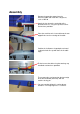
Assembly Remove the protective paper from the aluminium table and clean with a degreaser, such as WD-40 Attach the four feet to the underside of the planer/thicknesser, using the cap head screws and washers provided. Place the machine on its feet and locate the two tapped holes on the rear edge of the table Position the shallow-tee shaped piece of metal so that the holes line up with those in the table edge. Fit the fence to the table using the two long cap head bolts and washers provided.
Slide the hole at the end of the bridge guard support arm over the pivot shaft and secure the guard by screwing the large yellow knob onto the threaded spindle. This knob is used to lock the arm at the desired angle. The bridge guard slides sideways and can be locked in place with this knob. The angle of the bridge guard can be adjusted with the yellow knob on the side of the arm. This guard and extraction outlet must be fitted onto the thicknessing table during planning operations.
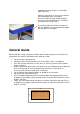
For thicknessing operations, the guard is fixed on top of the tables, as show. It is secured by screwing the two yellow knobs into two threaded holes in the table. Again, an audible ‘click’ can be heard as the interlock switch is activated by the guard.
Planing Function Fit the guard and extraction outlet onto the thicknessing table and lock it into place. Set The Angle Of The Guide Fence The guide fence can be set to any angle from 90 degrees to 45 degrees. There are pre-set stops for those two positions. The guide fence is locked and unlocked by using this lever. Any other angle can be set by reading off the scale. Set The Depth Of Cut Turn the yellow knob, located on the end of the infeed table, clockwise to decrease the depth of cut.
support the piece by hand as a second drive roller feeds it out. Repeat as many times as necessary to achieve the required dimensions of the piece. Each time, rotate the crank handle clockwise one turn to raise the bed by 2mm, or read the actual dimension off the scale. The out-feed end of the thicknesser bed has a pull out support that can be extended to support the work piece as it emerges.
Knife Removal and Replacement Out-feed table In-feed table Locking bar bolts Locking bar Knife Cutter block Using the 8mm spanner provided, turn the bolts clockwise so that you screw them into the locking bar. When you have done this with all 6 of them, you may lift out the locking bar and knife. Be aware that there are two small springs underneath the knife. Remove it slowly so that you do not lose these.
Troubleshooting Problem Machine does not start Cause Blown Fuse Loose switch terminal Faulty switch Guard not fitted Only starts when Green button is held down Machine runs intermittently Motor running but cutterblock is not rotating Motor slows down during the cut Faulty switch Remedy Replace Fuse Inspect back of switch Replace switch Re-fit the plastic guard ensuring it connects with the interlock switch Replace switch Worn carbon brushes in motor Broken or stretched drive belt Replace motor brushes
Charnwood W588 Parts Diagram
Charnwood, Cedar Court, Walker Road, Hilltop Industrial Estate, Bardon, Leicestershire, LE67 1TU Tel. 01530 516 926 Fax. 01530 516 929 email: sales@charnwood.net website: www.charnwood.