Machinery & Tooling at its best! 10” BANDSAW OPERATING INSTRUCTIONS MODEL: W715 Charnwood, Cedar Court, Walker Road, Bardon, Leicestershire, LE67 1TU Tel. 01530 516926 Fax. 01530 516929 email; sales@charnwood.net website; www.charnwood.
GENERAL SAFETY RULES WARNING: Do not attempt to operate the machine until you have thoroughly read and understood completely all instructions, rules, etc. contained in this manual. Failure to comply may result in accidents involving fire, electric shock, or serious personal injury. Keep this owner's manual and review frequently for continuous safe operation. 1. Know your machine. For your own safety, read the owner's manual carefully.
17. Never leave the machine running unattended. Turn the power off. Do not leave the machine until it comes to a complete stop. 18. Do not use any power tools while under the effects of drugs, alcohol or medication. 19. Always wear a face or dust mask if operation creates a lot of dust and/or chips. Always operate the tool in a well ventilated area and provide for proper dust removal. Use a suitable dust extractor. ADDITIONAL RULES FOR BAND SAWS 1.
Specification Table size 340 x 335 mm Motor 370W Blade length 1712 mm Blade speed (no load) 1400±10% m/min Blade widths 6 to 12 mm Maximum depth of cut at 90o 100mm Maximum depth of stock at 45o 70mm Throat capacity 250mm Dust extractor hose connection 40mm Weight 30kg net Features Precision ground, cast iron table with adjustable scale on rip fence carrier 0 to 45o table tilt High Quality, British made blade Easily portable machine Quick release, positive lock rip fence Cross cut/mitre
Unpacking Cut the strapping and remove the carton from the polystyrene insert. Remove all parts from the packaging Assembly Place the saw, so that it is lying on its back. Hold the table in place with the four threaded holes in line with the holes in the upper trunnion. Fix it in place with two of the four bolts and serrated washers provided Tilt the table and fit the remaining two bolts and washers, tightening the bolts after all four have been fitted.
Screw the four hex, headed bolts and washers into the tapped holes on the underside of the table and slide the rip fence carrier on to them. Make sure that it is a snug fit. If you do not keep it tight to the table the rip fence will not be perpendicular to the table. Make sure that the cut out in the carrier is aligned with the tee slot in the table or you will not be able to insert the crosscut/mitre fence. The scale is adjustable separately Check to see if the blade is centred in the slot.
The lower trunnion is attached to the body of the saw by four hex headed bolts. These may be slackened and the trunnion slid in either direction until the blade is centred. After adjustment, tighten them securely. Adjustable pointer. This lever locks and unlocks the trunnion so that the table may be tilted. Having set the table so that the blade is centred, apply a little tension to the blade and use a set square to position the table at right angles to it.
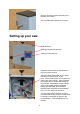
Screw in and lock the push stick hanger on the back of the frame. This completes the assembly of your saw. Setting up your saw Blade tensioner Blade guard positioner and lock Tracking control and lock Adjust the blade tension by hand wheel on top of the upper housing. ‘Pluck’ the back of the blade, as you would the string of a double bass, at this point. As the blade tension is increased, the pitch of the sound will rise. Stop increasing the tension as soon as the sound starts to become dull.
The upper and lower thrust bearings and guide pins should be set up next. Thrust bearing Guide pin Guide pin locking screw Thrust bearing locking screw The thrust bearing should be about 0.5 mm behind the back of the blade. Adjust it and lock it place. Slacken the guide pin locking screws, push the pins in until they touch the blade. Rotate the top wheel by hand a few turns and lock the pins in the position they have assumed. The lower thrust bearing and guide pins are adjusted similarly.
This bandsaw is equipped with a rip fence and a cross cut/mitre fence which can be fitted as shown. The rip fence may be used on either side of the blade and may also serve as a length stop for repetitive cross or mitre cuts. Your bandsaw is now ready for use but it is recommended that it be bolted to a bench and that a suitable dust extractor is connected.
Lower the upper blade guide Remove the rip fence carrier (shown here still in place) Slide blade off upper and lower wheels, bringing it out of the machine via the slots in the rear frame and the blade guard. Reverse these steps to fit the new blade. Ensure that the teeth are at the front and pointing down. Position the blade between the guide pins. Tension and adjust the tracking as done during the initial set up.
Parts List Item Description Quantity 1 2 3 4 5 6 7 8 9 10 11 12 13 14 15 16 17 18 19 20 21 22 23 24 25 26 27 28 29 30 31 32 33 34 35 36 37 38 39 40 41 42 43 44 45 46 47 48 Slotted Insert Washer Housing Washer Lower Door Housing, with nut Tongue Ext. lock washer 6mm Hex.
49 50 51 52 53 54 55 56 57 58 59 60 61 62 63 64 65 66 67 68 69 70 71 72 73 74 75 76 77 78 79 80 81 82 83 84 85 86 87 88 89 90 91 92 93 94 95 96 97 98 99 100 101 Lower trunnion Washer Cap head screw Thrust bearing retaining block Guide pin Thrust bearing shaft Thrust bearing Setting screw Hex. head bolt Table insert Table Coach bolt Guide piece Upper trunnion Indicator Tilt locking lever Hex. head bolt Nut Hex.
102 103 104 105 106 107 108 109 110 Spring washer Motor mounting plate Motor Motor cable Mains cable Nut Hex head bolt Strain relief Shaft 4 1 1 1 1 2 4 2 1 14
Machinery & Tooling at its best! Charnwood, Cedar Court, Walker Road, Bardon, Leicestershire, LE67 1TU Tel. 01530 516926 Fax. 01530 516929 email; sales@charnwood.net website; www.charnwood.