CPR-30201 Rack Mount LCD Keyboard Drawer 20.
Warranty The product is warranted against material and manufacturing defects for two years from date of delivery. Buyer agrees that if this product proves defective Chassis Plans’ is only obligated to repair, replace or refund the purchase price of this product at Chassis Plans’ discretion.
Trademarks Liability Disclaimer IBM, PC/AT, VGA, EGA, OS/2 and PS/2 are trademarks or registered trademarks of International Business Machines Corp. Intel is a registered trademark of Intel Corporation. MS-DOS and Microsoft are registered trademarks of Microsoft Corp. All other brand and product names may be trademarks or registered trademarks of their respective companies.
Chassis Plans CPR- 30201 Technical Reference Table of Contents Description ..................................................................................................................................1 Outline Drawing .....................................................................................................................2 Part Number Matrix.....................................................................................................................3 Keyboard Selection Options.....
Chassis Plans CPR- 30201 Technical Reference KVM Reference .....................................................................................................................20 Conventions ............................................................................................................................20 Introduction...............................................................................................................................21 Overview .........................................
Chassis Plans CPR-30201 Technical Reference Description The CPR-30201 is an ultra high performance rack mount 1U 20.1" TFT LCD display with UXGA 1600x1200 resolution. The display offers 250nit brightness, 500:1 contrast, and 89 degree viewing angle for exceptional viewability. An anti-glare hard coating minimizes reflections making images that much clearer. The aspect ratio is 4:3 with a Pixel Pitch of only 0.255mm. It will display 16.7 million colors (True Color 32-bit).
Chassis Plans CPR-30201 Technical Reference Outline Drawing Page 2
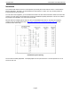
Chassis Plans CPR-30201 Technical Reference Part Number Matrix CPR-30201-K where ‘K is the keyboard model shown below Keyboard Selection Options ‘K’ 1U 4U 5U 6U 8U Keyboard Style Cherry 83 Key Cherry 83 Key Nema 4 Sun Nema 4 – 113 Key Pointing Device Trackball Glide Point Pressure Sensitive Pointing Device Trackball Hula Point Keyboard Options 1U - USB 4U - USB 5U - USB 6U - USB 8U - USB Cherry 83 key Keyboard with high quality 16mm integrated trackball and two button pointing device.
Chassis Plans CPR-30201 Technical Reference Installation To mount the CPR-30201 in a rack, it is first important you identify the correct holes to mount to. Please see the following illustration. Note that a ‘U’ starts between the holes that are ½” apart. One very common problem is trying to install into the wrong holes. For most rack mount equipment, you can install the fixed rails in the rack and then slide the chassis into those rails.
Chassis Plans CPR-30201 Technical Reference Connecting the Display The CPR-30201 provides for analog, digital, composite and S-Video video inputs as well as connections for the keyboard and mouse, and audio input and output. The CPR-30201 with KVM provides connectors mounted to the rear of the system and includes 72” cables that connect to the user equipment. Optional cable lengths, connectors, markings, etc. are available on special order.
Chassis Plans CPR-30201 Technical Reference Rear Panel Signal Connectors Cable Display End Cable Computer End - USB The CPR-30201 provides a front panel Source selection button for selecting which input signal is to be displayed. In addition, Picture-In-Picture is supported where the S-Video or Composite video inputs can be displayed as a small window on top of the aRGB or DVI-D inputs. An audio amplifier is provided with a computer input source and 2 RCA audio inputs for right and left channel.
Chassis Plans CPR-30201 Technical Reference Front Panel Controls The On Screen Display (OSD) is adjusted as follows: 1. 2. 3. 4. Press the Menu Button located on the front of the monitor. Use the buttons described below to maneuver around the Menu. Select the desired OSD Menu from the Menu Screen Shots below to make the desired adjustment(s). Press the Menu Button to exit out of the OSD Menu when complete or wait for the OSD window to automatically close as set by the OSD Time Out setting.
Chassis Plans CPR-30201 Technical Reference Sleep Mode The display will enter sleep mode (turn off) if there is no input signal to the selected input mode. The delay to enter Sleep Mode when the signal is not valid is approximately 6 seconds. When in sleep mode, the Power LED will flash green. Pressing the Power button or Source button will exit the Sleep Mode and the display will scan the selected input port for a signal. If no signal is present, the display will once again enter Sleep Mode.
Chassis Plans CPR-30201 Technical Reference OSD The CPR-30201 provides for On Screen Display (OSD) of the controls to adjust the display parameters such as brightness, contrast, etc. The menus are context sensitive in that there are adjustments specifically for each Source Input type (analog aRGB, digital DVI-D, S-Video and Composite). This allows you to tune the display for each type of input without having to retune when changing the Source selection.
Chassis Plans CPR-30201 Technical Reference A typical menu appears as follows: Display Menu Adjustment Brightness – Fine Brightness – Course Contrast Phase Frequency H Position V Position Sharpness Color Tint Brightness Contrast Phase Frequency H Position V Position Sharpness Color Tint aRGB ● ● ● ● ● ● ● Applicability DVI-D CVHS ● ● ● ● ● ● ● ● ● CVBS ● ● ● ● ● ● Top is Fine Adjustment and bottom is Course Adjustment. Adjusts the brightness of the screen.
Chassis Plans CPR-30201 Technical Reference PIP Menu Adjustment Brightness Contrast Sharpness Color Tint PIP Source PIP Size PIP More Settings (sub menu) Brightness Contrast Sharpness Color Tint PIP Source PIP Size PIP More Settings aRGB ● ● ● ● ● ● ● ● Applicability DVI-D CVHS ● ● ● ● ● ● ● ● CVBS Adjusts the brightness of the PIP display. Adjust distinction (Image noise clearness). Adjusts the sharpness of the PIP display. Adjusts the display color saturation of the PIP display.
Chassis Plans CPR-30201 Technical Reference OSD Menu Adjustment OSD Background OSD Time Out OSD Position Preset OSD H Position OSD V Position OSD Language Version 29A 1.00 OSD Background OSD Time Out OSD Position Preset OSD H Position OSD V Position OSD Language Version 29A 1.00 aRGB ● ● ● ● ● ● ● Applicability DVI-D CVHS ● ● ● ● ● ● ● ● ● ● ● ● ● ● CVBS ● ● ● ● ● ● ● Opaque or Translucent Sets the time (5 to 60 seconds) the OSD will be displayed without any user input.
Chassis Plans CPR-30201 Technical Reference Misc Menu Adjustment Auto Adjustment Source Sleep Time Room Lighting Freeze Frame Zoom Settings (sub menu) More Options (sub menu) aRGB ● ● ● ● ● ● ● Applicability DVI-D CVHS ● ● ● ● ● ● ● ● ● ● ● CVBS ● ● ● ● ● Automatically adjusts the screen resolution and sync to the incoming signal. (aRGB Source Only) Source Selects the video input signal source (aRGB, DVI-D, S-Video, and Composite Video).
Chassis Plans CPR-30201 Technical Reference Misc. More Options Sub Menu Adjustment Color Temp Red Temp Green Temp Blue Temp Sharpness Filter Scale Mode Factory Reset Color temp User color Sharpness Filter Scale Mode aRGB ● ● ● ● ● ● ● Applicability DVI-D CVHS ● ● ● ● ● ● ● ● ● ● ● ● ● ● CVBS ● ● ● ● ● ● ● Adjust the Red/Green/Blue bias for Color Temperature (5500K, 7500K, 9300K and User). Default value is set at 7300K.
Chassis Plans CPR-30201 Technical Reference Video Controller Details Features • State of the art high performance picture quality design • Analog RGB / DVI / CVBS (x1) & SVHS (x1) with NTSC, PAL, SECAM /Audio input (x3) / TV / Remote control / Speaker out (x1) • Optional input combination, e.g.
Chassis Plans CPR-30201 Technical Reference Controller Block Diagram Page 16
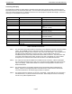
Chassis Plans CPR-30201 Technical Reference Video Mode Support The CPR-30201 monitor can support any video mode within the following input constraints: • Signal sample frequency with the input ≤ 80kHz • Horizontal sync frequency between 30KHz and 60KHz. The modes are detected when presented to the input and previous alignments for setup are automatically recalled. A true multi-sync monitor emulation is implemented. The factory preset supported modes include: Notes: 1.
Chassis Plans CPR-30201 Technical Reference Specifications ENCLOSURE 1U x 19" (wide) x 30" (deep) (Not including connectors) Fits 27”-36” Rack Weight: 30lbs Color: Powder coated black, light texture (Custom colors and logos available) DISPLAY LG.Phillips LM201U04 20.1" TFT LCD w/ antiglare hard coating Display area: 408mm x 306mm Display Colors: 16.7 Million Response Time: 16mS Viewing Angle: 89/89/89/89 deg Contrast Ratio: 500:1 typical Brightness: 250cd/m2 typical Pixel Pitch: 0.255mm x 0.
Chassis Plans CPR-30201 Technical Reference CONNECTORS: aRGB: DVI-D: Composite: S-Video In: Audio In: PC Audio In: Keyboard/Mouns: DC Power In: 15-pin high density DB15 DVI-D 23-pin female BNC 4-Pin Mini Din RCA (x2) 3.5mm Stereo Mini Jack Male USB 2-Pin 2x5.5 Power Plug POWER CONSUMPTION Normal: 60W (front LED Green) Power Input: 100-240VAC, 50/60Hz 1.2A Power Cord: Wall-outlet type or PC-outlet type The power supply is a Sunny model STD-1504 or equivalent "brick" measuring 2.5"(W) x 1.2"(H) x 4.3"(L).
Chassis Plans CPR-30201 KVM Technical Reference KVM Reference Conventions This KVM manual uses the following conventions: [ ] Indicates keys you should press. For example, [Enter] means to press the Enter key. If keys need to be chorded, they appear together in the same bracket with a plus sign between them: [Ctrl+Alt]. 1. Numbered lists represent procedures with sequential steps. • Bullet lists provide information, but do not involve sequential steps. � Indicates movement through a series.
Chassis Plans CPR-30201 KVM Technical Reference KVM Introduction Overview The KVMS-RGBA4 represents a revolutionary new direction in KVM (Keyboard, Video, Mouse) Switches. The KVMS-RGBA4 are dual function four Port KVM Switches combined with 2 Port USB Hubs. As KVM switches, they allow users to access four computers from a single USB keyboard, USB mouse, and monitor console.
Chassis Plans CPR-30201 KVM Technical Reference Features • • • • • • • • • • • • Dual function KVM-USB switch One console 4 computers and two additional USB devices Dual interface support -PS/2 or USB keyboard and mouse data transport* Independent (asynchronous) switching of KVM and peripheral USB ports Fully compliant with the USB 1.1 specification -supports transfer rates of 1.
Chassis Plans CPR-30201 KVM Technical Reference Cables Only C50X and C60X Custom cable sets specifically designed to work with this switch may be used to link to the computers. Four 1.2m 4-in-1 cable sets are provided with this package. They use the USB to transfer the keyboard and mouse input from your console to the computer. The switches also support computers that use PS/2 connectors to transfer keyboard and mouse data.
Chassis Plans CPR-30201 KVM Technical Reference Hardware Setup KVMS-RGBA4 Rear View 1. Console Audio Jacks The cables from your microphone and speakers plug in here. Each jack is marked with an appropriate icon to indicate itself. 2. USB Hub Section USB peripherals (printers, scanners, etc.) can plug into any available port. 3. Firmware Upgrade Section Firmware Upgrade Switch During normal operation this switch should be in the NORMAL position.
Chassis Plans CPR-30201 KVM Technical Reference Before you Begin 1. Make sure that power to all the devices you will be connecting up have been turned off. 2. To prevent damage to your installation make sure that all devices on the installation are properly grounded. Cable Connection To set up your KVMS-RGBA4 installation, refer to the installation diagrams on the following pages, and do the following: 1. Plug your monitor into the Console monitor port located on the unit’s rear panel. 2.
Chassis Plans CPR-30201 KVM Technical Reference USB Cable Connection PS/2 Cable Connection Page 26
Chassis Plans CPR-30201 KVM Technical Reference Hot Plugging The KVMS-RGBA4 supports USB hot plugging. Components can be removed and added back into the installation by unplugging their cables from the CPU ports without the need to shut the unit down. Powering Off and Restarting If it becomes necessary to Power Off the KVMS unit, before starting it back up you must do the following: 1. Shut down all the computers that are attached to the switch.
Chassis Plans CPR-30201 KVM Technical Reference Hotkey Operation The KVMS-RGBA4 provides an extensive, easy-to-use, hotkey function that makes it convenient to control and configure your KVM installation from the keyboard. Hotkeys provide asynchronous (independent) switching of the KVM, USB hub and audio focus. If you wish, you can give one computer the KVM console focus, another the USB hub focus, while a third has the audio focus.
Chassis Plans CPR-30201 KVM Technical Reference Going Directly to a Port Hotkey Action Brings the KVM, USB hub, and audio focus to the computer attached to the port corresponding to the specified Port ID.
Chassis Plans CPR-30201 KVM Technical Reference Hotkey Setting Mode (HSM) Hotkey Setting Mode is used to set up your KVMS-RGBA4 switch configuration. All operations begin with invoking Hotkey Setting Mode (HSM). Invoking HSM To invoke HSM do the following: 1. Press and hold down the Num Lock key 2. Press and release the minus key 3. Release the Num Lock key Note: 1. There is an alternate key combination to invoke HSM. See below for details. 2.
Chassis Plans CPR-30201 KVM Technical Reference Alternate Port Switching Keys The port switching activation keys can be changed from tapping the Scroll Lock key twice ([Scroll Lock] [Scroll Lock]) to tapping the Ctrl key twice. To change the port switching activation keys, do the following: 1. Invoke HSM 2. Press and release the T key Note: This procedure is a toggle between the two methods.
Chassis Plans CPR-30201 KVM Technical Reference List Hotkey Settings To see a listing of the current hotkey settings, do the following: 1. Invoke HSM. 2. Press and release the F4 function key. 3. Open a text editor or word processor and use its Paste function to display the settings. USB Reset If the USB looses focus and needs to be reset, do the following: 1. Invoke HSM. 2. Press and release the F5 function key. Hotkey Beeper Control The Beeper can be hotkey toggled On and Off.
Chassis Plans CPR-30201 KVM Technical Reference Restore Default Settings To reset the KVMS-RGBA4 to its default hotkey settings, do the following: 1. Invoke HSM. 2. Press [R] [Enter]. All hotkey settings return to the factory default settings.
Chassis Plans CPR-30201 KVM Technical Reference Keyboard Emulation Sun Keyboard The PC compatible (101/104 key) keyboard can emulate the functions of the Sun keyboard when the Control key [Ctrl] is used in conjunction with other keys. The corresponding functions are shown in the table below. Note:When using [Ctrl] combinations, press and release the Ctrl key, then press and release the activation key.
Chassis Plans CPR-30201 KVM Technical Reference Mac Keyboard The PC compatible (101/104 key) keyboard can emulate the functions of the Mac keyboard. The emulation mappings are listed in the table below. Note: When using key combinations, press and release the first key, then press and release the second one.
Chassis Plans CPR-30201 KVM Technical Reference Firmware Upgrade Utility The Firmware Upgrade Utility The Windows-based Firmware Upgrade Utility (FWUpgrade.exe) provides a smooth, automated process for upgrading the KVM switch’s firmware. The Utility comes as part of a Firmware Upgrade Package that is specific for each device. Before You Begin 5. Choose the Firmware Upgrade Package you want to install (usually the most recent), and download it to your computer. Power off the switch.
Chassis Plans CPR-30201 KVM Technical Reference Starting the Upgrade To upgrade your firmware: 1. Run the downloaded Firmware Upgrade Package file -either by double clicking the file icon, or by opening a command line and entering the full path to it. 2. The Firmware Upgrade Utility Welcome screen appears: Note: The screenshots in this section are for example purposes. The screens that appear during your firmware upgrade may vary slightly as to their wording and descriptions. 1.
Chassis Plans CPR-30201 KVM Technical Reference If you didn’t enable Check Firmware Version, the Utility installs the upgrade files without checking whether they are a higher level, or not. As the Upgrade proceeds status messages appear in the Status Messages panel, and the progress toward completion is shown on the Progress bar. Upgrade Successful After the upgrade has completed, a screen appears to inform you that the procedure was successful. To complete the upgrade: 1.
Chassis Plans CPR-30201 KVM Technical Reference Appendix KVM Specifications Function KVMS-RGBA4 Computer Connections 4 CPU Port Selection Front Panel Switches; Hotkey USB Port Selection Console Keyboard Connectors Mouse Hotkey Video Audio CPU Connectors KVM data Audio 1 x USB Type A (Integrated inside) 1 x USB Type A (Integrated Inside) 1 x HDB -15 female 1 x Stereo port 1 x Microphone port 4 x SPDB -15 female 4 x Stereo ports 4 x Microphone ports USB Peripherals 2 x USB Type A Firmware Upgra
Chassis Plans CPR-30201 KVM Technical Reference Troubleshooting Symptom Possible Cause Action Keyboard and/or Mouse not responding. Keyboard and/or mouse need to be reset. Press and hold port selection switches 1 and 2 for two seconds No connection to the computer. Unplug the cable(s) from the console port(s), then plug it/them back in. Check the cable from the switch to the computer to make sure it is properly connected.