MP1X17A™ Rugged Portable Computer TECHNICAL REFERENCE Revision A 1
MP1X17A Technical Reference WARRANTY The following is an abbreviated version of Chassis Plans’ warranty policy for portable products. For a complete warranty statement, contact Chassis Plans or visit our website at www.chassis-plans.com. Chassis Plans Portable Computing products are warranted against material and manufacturing defects for 1 (one) year from date of delivery to the original purchaser.
MP1X17A Technical Reference TRADEMARKS Chassis Plans®, The Original Industrial Computer Source®, Systems Engineered to Perform™ and MP1X17A™ are trademarks or registered trademarks of Chassis Plans. IBM, PC/AT, VGA, EGA, and PS/2 are trademarks or registered trademarks of International Business Machines Corp. Intel is a registered trademark of Intel Corporation. MS-DOS and Microsoft are registered trademarks of Microsoft Corp.
MP1X17A Technical Reference Handling Precautions STATIC ELECTRICITY WARNING This product contains components which may be damaged by electrostatic discharge. When the system is assembled and the rear cover is installed, the system is inherently immune to electrostatic discharge. It is always a good idea to ground yourself to a metal part of the frame before connecting cables and do not discharge static into a connector.
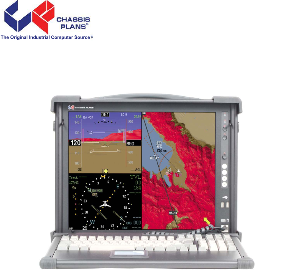
MP1X17A Technical Reference Chapter 1 - Introduction / Specifications Chapter 1 – Introduction / Specifications Chassis Details The MP1X17A Rugged Enterprise Class portable computer is designed to meet the needs of Mission Critical Applications, providing configurations that are truly Fit-for-Use in a variety of operating environments and with a wide range of options to serve the most demanding requirements.
MP1X17A Technical Reference Chapter 1 - Introduction / Specifications Features 17" SXGA 1280x1024 LCD Anti-glare tempered glass shield to protect LCD Rugged aluminum alloy construction Designed for harsh environments Fits ATX motherboard 7 Plug-in card slots Two external 5-1/4" drive slots One external 3-1/2" drive slot One external Slim DVD drive slot Built-in speaker w/ amplifier & volume controls Two high flow cooling fans Detachable 108 key keyboard w/ touch pad Various power
MP1X17A Technical Reference Chapter 1 - Introduction / Specifications Power Supply The MP1X17A uses a standard PS/2 style power supply. Several options are available for AC and DC input including redundant supplies. The system is normally configured with a minimum 650W single supply with auto-ranging 90-265VAC (46-66Hz) input. This allows the system to be used world-wide without regard to the power available. Contact the factory for other AC, DC and redundant power supply options.
MP1X17A Technical Reference Chapter 1 - Introduction / Specifications Specifications Chassis Motherboard Cooling Display Integrated Peripherals Input Peripheral Environmental Specifications Power Supply Dimensions Weight Transport Case Chassis Plans External Chassis Internal Chassis Form Factor Card Slots I/O Fans LCD Resolution Color Viewing Angle Brightness Contrast Ratio Response Time Aspect Ration Backlights Drives Aluminum extrusion/aluminum alloy with rubber corners Aluminum alloy frame AT
MP1X17A Technical Reference Chapter 1 - Introduction / Specifications 2.
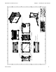
Chassis Plans 15.08 7x ADD−IN CARD SLOTS PS/2 POWER SUPPLY ATX MOTHERBOARD I/O AREA 9.00 14.06 17" TFT LCD 1280X1024 17.09 17.
MP1X17A Technical Reference Section 2 - Operation Chapter 2 - Operation 2.1 Release the Keyboard from main unit by pressing the 2 buttons located on each side of the keyboard to release the locking mechanism, and then pull out the keyboard. Lift Up Lift Up 2.2 You have the option of leaving the keyboard attached to the chassis or it can be released independently from the chassis by pushing the two bottom levers inward to release the lock.
MP1X17A Technical Reference Section 2 - Operation 2.3 Connect the keyboard/touchpad cable to the RJ45 connector at the front bottom right corner of the chassis. Make sure the pin direction is correct when inserting. Note that the keyboard can be closed without disconnecting this plug. 2.4 You can flip the 2 feet located underneath the chassis outward to help create an angle (8 degrees) for the chassis for viewing comfort. Locate the feet and flip outward until they click into place.
MP1X17A Technical Reference Section 2 - Operation 2.5 Connect the power cable into the power supply unit in the main chassis on the left. Insert Power Cord 2.6 Press the power button in the front right panel of the chassis to power up the unit.
MP1X17A Technical Reference Section 2 - Operation 2.7 The right front panel of the chassis provides access to the indicator lights, reset, power and USB ports. PWR LED HDD LED Reset Button LCD On/Off Button Power Button LCD OSD Button USB Ports 2.8 The left side of the chassis provides access to the plug-in card expansion slots, motherboard I/O and AC power connector.
MP1X17A Technical Reference Section 2 - Operation 2.9 Two cooling fans are located in the chassis, one located on the rear and another on right side. 2.10 Access to the system board I/O panel is on the bottom left side of the chassis.
MP1X17A Technical Reference Section 2 - Operation 2.11 Acces to the optical drive and any removable drive kit or drive mounting device is on the right hand side of the chassis. 3.5” Drive Mounting Slim DVD Mounting 5.25” Drive mounting 2.12 There are four buttons located on the right side of the LCD. Use the LCD OSD to adjust the display to match your video board via the OSD buttons. Press the MENU button to bring up the on screen menu and then follow the instructions.
MP1X17A Technical Reference Chapter 3 – Internal Hardware Access Chapter 3 – Internal Hardware Access WARNING Be sure the power cable is not connected to the system before proceeding. Even with the power “turned off”, the power supply will be supplying standby voltages to the motherboard and installing components to an energized motherboard may damage the motherboard, components or both. WARNING Components inside the system are subject to static discharge damage.
MP1X17A Technical Reference Chapter 3 – Internal Hardware Access 3.2 Remove the 4 screws to remove the stabilizer bar from the chassis to access the internal chassis. Unscrew Unscrew 3.3 Remove the left side cover plate by unscrewing the 3 hex screws on the left side. Lift off the plate when loose.
MP1X17A Technical Reference Chapter 3 – Internal Hardware Access 3.4 Remove the 4 screws on the chassis to remove the power supply unit from the chassis. Unscrew Unscrew Unscrew Unscrew 3.5 Remove the right side cover plate by unscrewing the 2 hex screws on the right side.
MP1X17A Technical Reference Chapter 3 – Internal Hardware Access 3.6 Remove the right side cover door by lifting off. 3.7 Remove the 2 mounting screw and slide the drive cage outward from its rail.
MP1X17A Technical Reference 3.8 Chapter 3 – Internal Hardware Access Install the motherboard I/O shield plate on the left side of the chassis opening and the proper standoff mounting according to the motherboard mounting requirements. Be careful a standoff is not touching any traces or components and that each standoff matches a hole in the motherboard. Unscrew Standoff Mount I/O Plate Location 3.9 Remove the 4 screws for holder of the internal removable tray assembly. 3.
MP1X17A Technical Reference Chapter 3 – Internal Hardware Access 3.10 You can remove the 3.5” attachment alone by removing the bottom assembly. The Slim DVD can also be optional. Unscrew 3.11 Install your add-in cards as necessary and secure tightly.
MP1X17A Technical Reference Chapter 3 – Internal Hardware Access 3.12 Fit the VGA or DVI cable through the top the slot first prior to installation display card and connect the header. Fit Video Cable Through Slot 3.13 Reassemble chassis in reverse order. It is important to neatly dress any wires and cables to protect them from damage and to not impact the cooling air flow. Taking the time to do a neat job will make your system more reliable.
MP1X17A Technical Reference Chapter 4 - Maintenance Chapter 4 - Maintenance While the MP1X17A system is ruggedly designed and constructed, it is still a sensitive computing device and should be treated accordingly. Do not subject it to abuse such as dropping it or letting it bounce around in the back of a vehicle. It does not need to be babied but, on the other hand, it does need to be carefully handled to assure reliable operation. It is a fairly large, unwieldy, and heavy device. 4.
MP1X17A Technical Reference Chapter 5 - Troubleshooting Chapter 5 - Troubleshooting The following are quick problem solving tips. Please contact Chassis Plans Customer Service Department at Service@chassisplans.com or by calling 858-571-4330 for technical assistance. Note: Unplug the power cord before servicing internal components to prevent damage. The power supply will provide standby power to the motherboard even when ‘Off’.
MP1X17A Technical Reference Chapter 5 - Troubleshooting 5.4 No internal display (LCD): 1. Check that all the proper power up procedures have been performed. 2. Connect an external CRT to the VGA port to check if video is present. 3. If video is present on external CRT, check the internal LCD cable connection. 4. Check your VGA setting using an external display to make sure LCD video is enabled. 5. If there is no video on external, check your system to make sure everything is seated properly. 6.
MP1X17A Technical Reference Chapter 6 – Packing List Chapter 6 – Packing List Package Contents Description Qty 1 User’s Manual User’s Reference Guide 1 2 ESD Bag ESD Bag for additional packaging 1 3 Power Cord Power Cord 1 4 Screw Pack Screw Pack (stabilizer) 1 5 Stabilizer Supports Pack Additional clip for card holder to secure add-in card 1 6 Hardware Pack (system) Additional cabling for internal interconnect 1 7 MP1X17A System Main system unit chassis 1 8 Carrying Bag