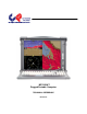
MP1X20A™ Rugged Portable Computer TECHNICAL REFERENCE Revision A
MP1X20A Technical Reference Warranty The following is an abbreviated version of Chassis Plans’ warranty policy for portable products. For a complete warranty statement, contact Chassis Plans or visit our website at www.chassis-plans.com. Chassis Plans Portable Computing products are warranted against material and manufacturing defects for 1 (one) year from date of delivery to the original purchaser.
MP1X20A Technical Reference TRADEMARKS Chassis Plans®, The Original Industrial Computer Source®, Systems Engineered to Perform™ and MP1X20A™ are trademarks or registered trademarks of Chassis Plans. IBM, PC/AT, VGA, EGA, and PS/2 are trademarks or registered trademarks of International Business Machines Corp. Intel is a registered trademark of Intel Corporation. MS-DOS and Microsoft are registered trademarks of Microsoft Corp.
MP1X20A Technical Reference Handling Precautions STATIC ELECTRICITY WARNING This product contains components which may be damaged by electrostatic discharge. When the system is assembled and the rear cover is installed, the system is inherently immune to electrostatic discharge. It is always a good idea to ground yourself to a metal part of the frame before connecting cables and do not discharge static into a connector.
MP1X20A Technical Reference Chapter 1 – Introduction / Specifications Chapter 1 – Introduction / Specifications Chassis Details The MP1X20A Rugged Enterprise Class portable computer is designed to meet the needs of Mission Critical Applications, providing configurations that are truly Fit-for-Use in a variety of operating environments and with a wide range of options to serve the most demanding requirements.
MP1X20A Technical Reference Chapter 1 – Introduction / Specifications Features 20.
MP1X20A Technical Reference Chapter 1 – Introduction / Specifications Power Supply The MP1X20A uses a standard PS/2 style power supply. Several options are available for AC and DC input including redundant supplies. The system is normally configured with a minimum 650W single supply with auto-ranging 90-265VAC (46-66Hz) input. This allows the system to be used world-wide without regard to the power available. Contact the factory for other AC, DC and redundant power supply options.
MP1X20A Technical Reference Chapter 1 – Introduction / Specifications Specifications External Chassis Aluminum extrusion/aluminum alloy with rubber corners Internal Chassis Aluminum alloy frame Form Factor ATX 9.6x12-inches Card Slots 7 externally accessible (left side of chassis) I/O Externally accessible motherboard I/O shield Cooling Fans 2x 120mm external fans 2x 80mm internal fans Display LCD 1x 20.1" SXGA TFT Resolution 1600x1200 Color 16.
MP1X20A Technical Reference Environmental Specifications Chapter 1 – Introduction / Specifications Temperature -10° C to +55° C operating -40 to +65° C non-operating Relative Humidity 5-95% (non-condensing) Shock 10G operating, all axes 30G non-operating, all axis Vibration 1.25G @ 10-100Hz operating, all axes 3.
MP1X20A Technical Reference Chapter 1 – Introduction / Specifications 2.
AUTO MENU S Video Composite Chapter 1 – Introduction / Specifications Component MP1X20A Technical Reference Chassis Plans 7
MP1X20A Technical Reference Chapter 2 - Operation Chapter 2 - Operation The MP1X20A is a well-designed compact portable computing machine that is both nimble as well as rugged. It will serve your needs for expansion as well as performance. An important aspect of the MP1X20A is the concept of standardization, which means all components that you can find off the shelf or of proprietary design will fit into the MP1X20A.
MP1X20A Technical Reference Chapter 2 - Operation Drive Bays Right Side: 1x 5-1/4” Drive Bay 4x Removable 3-1/2” Drive Bays Left Side: 2x Removable 3-1/2” Drive Bays 1x Slim DVD 1x Slim Floppy Right Side View Left Side View Keyboard 108 key full-travel keyboard is integrated with the MP1X20A and attaches to the front. It may be used while connected or removed. This provides storage for the keyboard as well as protection for the LCD while in transit.
MP1X20A Technical Reference LED Status Indicators The front panel provides two LED indicators. indicates hard disk drive access. Chapter 2 - Operation The green LED indicates power on. The red LED Display Integrated TFT Active Matrix LCD provides UXGA 1.6M color display with resolution of 1600*1200. Brightness is 300nits with an 800:1 contrast ratio and 5mS response. The LCD is provided with a protective glass overlay with an anti-glare coating. A standard OSD allows fine tuning the display parameters.
MP1X20A Technical Reference Chapter 2 - Operation 2.1 Keyboard and Touch pad How to release the Keyboard There are two release buttons located on the top-left and top-right of the chassis. When pushed, the keyboard is disengage from the MP1X20A and will swing down. There are also two spring pins located at the bottom of the keyboard that are inserted into the MP1X20A. Pressing these inward will release the keyboard entirely from the MP1X20A.
MP1X20A Technical Reference Chapter 2 - Operation Touchpad operation The TouchPad surface can be used to move the cursor in the GUI environment by placing and moving your finger. The two buttons located below the touch pad act as same as the mouse left/right button. Or you may wish to tap on the touch pad to indicate a left click. Note the proper pointing device (TouchPad) drivers must be installed for the operating system to recognize and take full advantage of the features of the TouchPad.
MP1X20A Technical Reference Chapter 2 - Operation 2.2 Right Side Panel There are four 3.5” removable drive trays and one regular 5.25” bay on the right side. The right side also provides the volume controls for the speaker. 2.3 Power Switch and AC Plug The power receptacle is located on the rear panel of the machine near the left side. A standard three-prong power plug is provided. Make sure the power switch on the power supply, if provided, is in the ON position before closing the rear panel.
MP1X20A Technical Reference Chapter 2 - Operation 2.5 Connecting an External Monitor An external monitor or projector can be hooked up via the side panel VGA (15pin) port while the system is off. The Display/Projector will provide the cable to be inserted into this port. When connected, the display should appear if the machine is powered on. The signal is standard with the internal viewing resolution and the default setting is simultaneous display on both MP1X20A’s LCD and CRT.
MP1X20A Technical Reference Chapter 2 - Operation 2.7 Speaker Volume Adjustment There are two volume adjustments (Increase/Decrease) on the right side panel. 2.8 Slim Size CD-ROM & FDD Drive Bays The left side, bottom, provides for mounting a slim DVD and slim Floppy drive.
MP1X20A Technical Reference Chapter 2 - Operation 2.9 Bottom Feet The bottom of the MP1X20A provides two feet that can be lowered to tilt the unit back. This makes for easier use of the LCD. 2.10 VGA & OSD The left side provides auxiliary video inputs (depending on your model) of Composite, S-Video or Component. The left side also provides the OSD controls for the LCD controller.
MP1X20A Technical Reference Chapter 2 - Operation 2.11 Front Panel USB Ports There are two USB ports on the front panel. These are connected to the motherboard internally and can be used for devices such as thumb drives, external hard drives, alternative keyboards or pointing devices such as track balls or joy sticks. Front Panel USB Ports 2.12 Cooling Fans The system is provided with two cooling fans, mounted on the right side and rear of the chassis.
MP1X20A Technical Reference Chapter 3 – Internal Access Chapter 2 – Internal Access WARNING Be sure the power cable is not connected to the system before proceeding. Even with the power “turned off”, the power supply will be supplying standby voltages to the motherboard and installing components to an energized motherboard may damage the motherboard, components or both. WARNING Components inside the system are subject to static discharge damage.
MP1X20A Technical Reference Chapter 3 – Internal Access 3.
MP1X20A Technical Reference Chapter 3 – Internal Access 3.3 Remove the Side Vertical HDD Bays Unscrew x2 Unscrew x2 3.4 Install System Board with CPU and RAM Configure your motherboard per the manufacturer’s instructions. Be careful to handle the motherboard per accepted anti-static practice to prevent damage. Do not handle the motherboard by the processor heat sinks as that can damage the processors and sockets.
MP1X20A Technical Reference Chapter 3 – Internal Access 3.5 Connect Keyboard and TouchPad Cables Connect the Keyboard and Touchpad cables to the appropriate connectors on the motherboard I/O area. Keyboard & Touchpad Connections 3.6 Connect Power, LED, and Speaker Wires Motherboard Control Connections Please refer to your System Board Manual for the actual location and pin-outs for the various chassis control connections for the Power Switch, LEDs, and Audio Output.
MP1X20A Technical Reference Chapter 3 – Internal Access 3.7 Accessing the Removable Hard Drives Loosen the drive retention screw. Drive Retention Screws Pull out the door cover. This unlocks the drive from the chassis. Pull out the drive tray. Mount the drive in the tray using the screws provided with the drive. Reinstall in reverse order.
MP1X20A Technical Reference Chapter 3 – Internal Access 3.8 Accessing the 5.
MP1X20A Technical Reference Chapter 3 – Internal Access 3.9 Accessing the Slim DVD & FDD Remove the 4 screws from the bottom as shown. 4x 4xScrews Screw Remove the 2 allen head screws (2mm) from the cover as shown. Then remove the 2 allen head screws (3mm) from the side cover. 2x Screws 2mm 2x Screws 3mm Last, remove the philips head screw as shown. This will allow the drive cage for the slim drives to be removed. Reinstall in reverse order.
MP1X20A Technical Reference Chapter 4 - Maintenance Chapter 4 - Maintenance While the MP1X20A system is ruggedly designed and constructed, it is still a sensitive computing device and should be treated accordingly. Do not subject it to abuse such as dropping it or letting it bounce around in the back of a vehicle. It does not need to be babied but, on the other hand, it does need to be carefully handled to assure reliable operation. It is a fairly large, unwieldy, and heavy device. 4.
MP1X20A Technical Reference Chapter 5 - Troubleshooting Chapter 5 - Troubleshooting The following are quick problem solving tips. Please contact Chassis Plans Customer Service Department at Service@chassisplans.com or by calling 858-571-4330 for technical assistance. Note: Unplug the power cord before servicing internal components to prevent damage. The power supply will provide standby power to the motherboard even when ‘Off’.
MP1X20A Technical Reference Chapter 5 - Troubleshooting 5.5 External CRT no display: 1. Check to see if you have internal LCD video. 2. Check if your CRT is functioning properly (connect to another computer). 3. Check your VGA setting to make sure external video is enabled. 5.6 Keyboard fails: Note: Typically, if the keyboard fails due to a faulty connection, the TouchPad will also not work. If one or the other device works, then it is a failed keyboard issue or a driver issue. 1. 2. 3. 4. 5.
MP1X20A Technical Reference Chapter 5 - Troubleshooting Chapter 6 – Packing List Package Contents Description Qty 1 User’s Manual User’s Reference Guide 1 2 ESD Bag ESD Bag for additional packaging 1 3 Power Cord Power Cord 1 4 Screw Pack Screw Pack (stabilizer) 1 5 Stabilizer Supports Pack Additional clip for card holder to secure add-in card 1 6 Hardware Pack (system) Additional cabling for internal interconnect 1 7 MP1X20A System Main system unit chassis 1 8 Carrying Ba