CPI KVM Switch User Manual Version 1.0 November 2011 800-834-4969 techsupport@chatsworth.com www.chatsworth.com ©2011 Chatsworth Products, Inc. All rights reserved. CPI, CPI Passive Cooling, MegaFrame, Saf-T-Grip, Seismic Frame, SlimFrame, TeraFrame, GlobalFrame, Cube-iT Plus, Evolution, OnTrac, QuadraRack and Velocity are federally registered trademarks of Chatsworth Products, Inc. Simply Efficient is a trademark of Chatsworth Products, Inc. All other trademarks belong to their respective companies.
Table of Contents Legal Information............................................................................................................................. 3 Warranty .......................................................................................................................................... 3 Introduction ..........................................................................................................4 Product Features – IP KVM Switch with DB15 Ports (P/N 37212-260).............
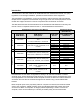
Chatsworth Products, Inc. 9353 Winnetka Avenue Chatsworth, CA 91311 800-834-4969 CPI KVM Switch User Manual ©2011 Chatsworth Products, Inc. All rights reserved. Legal Information The information contained in this guide is subject to change without notice. Chatsworth Products, Inc.
Introduction This document is the User’s Manual for KVM Switches from Chatsworth Products, Inc. (CPI). It guides the user through installation, operation and maintenance of the equipment. The KVM Switch is a standalone, rack-mount keyboard, video and mouse switch that allows multiple server computers to be accessed using a single set of rack-mount peripherals. Some models also support access for a remote computer and/or an Ethernet connection.
Product Features – IP KVM Switch with DB15 ports (P/N 37212-260) • 16 DB15 KVM switch device ports which provide low-level keyboard, video and mouse connectivity to equipment within a rack. KVM Switches with DB15 ports use a proprietary 6 feet (1.8 meters) or 10 feet (3.0 meters) long breakout cable to connect computers. Cables are purchased separately (P/N 37203-161 or 37208-111). • Buttons on the front panel allows easy switching between computer ports.
Product Features – Analog KVM Switch with DB15 ports (P/N 37202-160) • Used primarily as expansion switches for other KVM Switches with DB15 ports and 17” LCD KVM Drawer and Switches with DB15 ports. • 16 DB15 KVM switch device ports which provide low-level keyboard, video and mouse connectivity to equipment within a rack. KVM Switches with DB15 ports use a proprietary 6 feet (1.8 meters) or 10 feet (3.0 meters) long breakout cable to connect computers.
Product Features – IP KVM Switch with Cat5/6 ports (P/Ns 37207-360, 37207-420) • 16 or 32 Cat5/6 RJ45 KVM switch device ports which provide low-level keyboard, video and mouse connectivity to equipment within a rack. KVM Switches with Cat5/6 ports use standard Cat5/6 UTP cabling with RJ45 connectors and dongles to connect computers, which allow computers to be located much farther from the switch, up to 132 feet (40 meters) away. Dongles (P/N 37208-103 or 37208-104) are purchased separately.
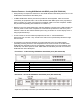
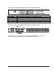
Front Panel - 16 Port IP KVM Switch with Cat5/6 ports (P/N 37207-360) Bank no.
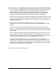
Front Panel - 32 Port IP KVM Switch with Cat5/6 ports (P/N 37207-420) Bank no.
Product Features – Analog KVM Switch with Cat5/6 ports (P/Ns 37210-260, 37210-220) • Used primarily as expansion switches for other IP KVM Switches with Cat5/6 ports and 17” LCD KVM Drawer and IP Switches with Cat5/6 ports. • 16 or 32 Cat5/6 RJ45 KVM switch device ports which provide low-level keyboard, video and mouse connectivity to equipment within a rack.
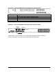
Front Panel - 16 Port Analog KVM Switch with Cat5/6 ports (P/N 37210-260) Bank no.
Front Panel - 32 Port Analog KVM Switch with Cat5/6 ports (P/N 37210-220) Bank no.
Important Safeguards Please read all of these instructions carefully before you use the device. Save this manual for future reference. Safety Instructions • Unplug equipment before cleaning. Don’t use liquid or spray detergent; use a moist cloth. • Keep equipment away from excessive humidity and heat. Preferably, keep it in an air-conditioned environment with temperatures not exceeding 40º Celsius (104º Fahrenheit).
Federal Communications Commission (FCC) Regulatory Notices This equipment has been tested and found to comply with the limits for a Class B digital device, pursuant to Part 15 of the FCC rules. These limits are designed to provide reasonable protection against harmful interference in a residential installation. Any changes or modifications made to this equipment may void the user’s authority to operate this equipment.
Installation Unpacking/ Package Contents Standalone KVM Switches come with the parts shown below. Check and make sure they are included and in good condition. If anything is missing or damaged, please contact the supplier immediately. Items 7-10 are only included with KVM Switches (P/Ns 37207-XXX, 37210-XXX). KVM Switch 1. LCD KVM Switch x 1 pc 2. Screw, M3 x 4.5 mm x 2 pc 3. Screw, M4 x 10mm x 8 pc 4. Mounting Brackets x 1 set 5. Power adapter x 1 pc (Not included with P/N 37202-160) 6.
Rack/Cabinet Installation Attach the rack-mount brackets to the KVM switch using the included screws. Attach the switch to a rack or cabinet. Rack-mount hardware is not included with the switch.
Cable Diagram for KVM Switches with DB15 ports Each server connects to the KVM Switch with DB15 ports with a Combo KVM Cable (P/N 37208-161 or 37208-111), ordered separately. Order one Combo KVM Cable per server. Combo KVM Cables are available in two lengths and are sold individual, in packages of eight and in packages of 16. Note: Analog KVM Switch (P/N 37202-160) does not have IP connections.
Cable Diagram for KVM Switches with Cat5/6 ports Each server connects to the KVM Switch with Cat5/6 ports with a Cat5/6 UTP cable that has RJ45 connectors and an IP KVM Cable Dongle. Order one IP KVM Cable Dongle per server to match the server’s keyboard and mouse type: PS/2 (P/N 37208-104) or USB (P/N 37208-103). The switch also has a remote console connection and includes the receiver and cables for attaching the remote computer. All switches have local consoles. Some switches also have IP consoles.
Server Connections for KVM Switches with Cat5/6 ports Servers connect to the KVM Switches with Cat5/6 ports using a dongle that makes the connection between the server’s video, keyboard and mouse connections and the UTP cable from the switch. Order the dongle to match the server’s video, mouse and keyboard connection. VGA-USB dongle (P/N 37208-103, 37208-803, 37208-603) • Connect server with DB15 video connector and USB mouse and keyboard to the UTP cable from the KVM Switch with Cat 5/6 ports.
Remote Console Connection for KVM Switches with Cat5/6 ports Each KVM switch with Cat5/6 ports also has one remote console connection and includes a remote console receiver to connect a separate set of peripherals or computer for switch access. Connect the remote console with a Cat5/6 UTP cable.
Cascade – Expansion for KVM Switches with DB15 ports Cascade up to seven additional Analog KVM Switches with DB15 ports (P/N 37202-160) to connect up to 128 servers through a single set of peripherals and IP address. The cascade cable attaches between the cascade port on the first switch and the local console on the next switch.
Cascade – Expansion for KVM Switches with Cat5/6 ports Cascade up to seven additional Analog KVM Switches with Cat 5/6 ports to connect up to 128 or 256 servers through a single set of peripherals, a single remote terminal or IP address. The Cascade Cable for KVM Switches with Cat 5/6 ports (P/N 37208-165) attaches between the cascade ports on the switches. Equipment is accessed through consoles on the first switch. The local, remote and IP connections on cascaded switches are not used.
Use – KVM Switch Power ON • • • Turn off all servers and KVM switches Make sure all cables / connectors are properly connected Recommend Power ON sequence is monitor, KVM switch finally computer 23
Password Configuration for the Local/Remote Console The password is disabled by default. • Enable password 1. Press the KVM hotkey Scroll Lock + Scroll Lock + U (you must press hotkey within 2 seconds, you will hear a beep when successful) 2. Logout the KVM by pressing the hotkey Scroll Lock + Scroll Lock + P (the unit will automatically log out after 10 minutes of inactivity) 3. In SUPERVISOR level, enter “00000000” eight zeros in user name & password field (Do not use “0” on number pad) 4.
The On Screen Display (OSD) Menu Access the OSD menu from the local console using the hot keys “scroll lock + scroll lock + space bar” or hold the right mouse button and hit the escape button. The OSD menu (shown below) displays.
The F1 Main Menu From the OSD menu, touch the F1 function key to access the main menu. The F1 Main Menu lets you set up the switch, assign port/computer names and create user accounts.
Local Console Hotkeys Hotkey Scroll Lock + Scroll Lock + Space Bar Right-button mouse + Esc Scroll Lock + Scroll Lock + Scroll Lock + Scroll Lock + Scroll Lock + Scroll Lock + PgUp / PgDn Scroll Lock + Scroll Lock + Bank Number + Port Number Scroll Lock + Scroll Lock + B Scroll Lock + Scroll Lock + P Function Calling OSD menu Calling OSD menu Switch to previous port Switch to next port Switch to previous bank or next bank Switch to specific port *Example SL + SL + 1 + 08 (bank 1, port 8) Turn the buzzer
Set up – IP Console The IP Console on KVM Switches are pre-configured with an IP address and password to allow quick setup and configuration. DHCP is not enabled. You can access the switch using a web browser. IP address 1: IP address 2: Subnet mask: Gateway Login Password 192.168.1.22 (Single IP Console) 192.168.1.23 (Second IP Console) 255.255.255.
5. Under Device, Click Refresh Devices to search for the connected IP KVM Switch. 6. Select the MAC address of the KVM Switch that you want to setup and click Query Device. (The MAC address of the KVM Switch is printed on the product label.) 7. To change the default password, under Authentication, a. Enter the Super user login. The default is super (all lower case) b. Enter the Super user password. The default is pass (all lower case) c. Enter the new super user password (this will change the password). d.
Troubleshooting guide – KVM Switch 1. There is no LED display on KVM membrane switch. • • • Make sure the power adapter is plugged into the KVM Switch. If the LED is still off, perform soft reset to KVM switch. If that does not work, power cycle the KVM switch. 2. I can power on the KVM, but I am not getting any picture. • • • • Switch to another port and check if this port has the same problem If the second port is working, check that the screen resolution is the same for both ports.
Appendices Factory Default Setting Local/Remote Console Login User name = 00000000 (eight zeros) Local/Remote Console Login Password = 00000000 (eight zeros) Menu Access key = Scroll Lock + Scroll Lock + Space Bar or Right Mouse Button + Escape IP Login User name = super (all lowercase) IP Login Password = user (all lowercase) Default IP address = 192.168.1.22 Default IP2 address = 192.168.1.23 FAQ Q. How do the KVM switches allow the user to switch ports? A.
Q. Why am I getting ghosting images or shadowing? A. The signal cable may be loose or the video card configuration may not match the switch. Check that all video cables are inserted properly. Check whether the KVM supports the resolution and refresh-rate on your servers. Check whether the graphics card you are using supports the resolution and refresh rate on your server or not. Connect the monitor directly into the servers you are having trouble with to see if problem still appears. Q.
Specifications – KVM Switches with DB15 ports KVM Ports: • Number of Ports, Connector: 16, DB15 • Connectivity: Combo KVM Cable up to 10 feet (3.0 meters) long, one per server; P/N 37208-161 for 6 feet (1.8 meters) long, P/N 37208-111 for 10 feet (3.
Specifications – KVM Switches with Cat5/6 ports KVM Ports: • Number of Ports, Connector: 16 or 32, RJ-45 (8P8C) • Connectivity: VGA connector dongle up to 132 feet (40 meters) over Cat6/Cat 5 UTP cable; order dongles separately, one per server, P/N 37208-103 for USB, P/N 37208-104 for PS/2 Local Console: • Graphic connector, resolution: 1 x DB15 VGA, up to 1600 x 1200 • Input Device: 2 x USB type A for keyboard and mouse Remote Console: • Connector: 1 x RJ45 (8P8C), up to 500 feet (150 meters) over Cat6/Cat
Accessories for KVM Switches with DB15 ports Combo KVM Cable, 6 feet (1.8 meter) long, P/N 37208-161, 1 each Combo KVM Cable, 6 feet (1.8 meter) long, P/N 37208-861, 8 pack Combo KVM Cable, 6 feet (1.8 meter) long, P/N 37208-661, 16 pack Combo KVM Cable, 10 feet (3.0 meter) long, P/N 37208-111, 1 each Combo KVM Cable, 10 feet (3.0 meter) long, P/N 37208-811, 8 pack Combo KVM Cable, 10 feet (3.
Accessories for KVM Switches with Cat5/6 ports VGA-USB Dongle, P/N 37208-103, 1 each VGA-USB Dongle, P/N 37208-803, pack of 8 VGA-USB Dongle, P/N 37208-603, pack of 16 For server connection, used to connect servers with VGA monitor and USB keyboard and mouse to the switch using a Cat 5/6 UTP cable with RJ45 connectors. Order one dongle per server. Order the UTP cable/patch cord separately.