Build To Spec Kit Aisle Containment Solution User’s Manual Version 1.0 December 2013 techsupport@chatsworth.com www.chatsworth.com ©2013 Chatsworth Products, Inc. All rights reserved. CPI, CPI Passive Cooling, GlobalFrame, MegaFrame, Saf-T-Grip, Seismic Frame, SlimFrame, TeraFrame, Cube-iT Plus, Evolution, OnTrac, Velocity and QuadraRack are federally registered trademarks of Chatsworth Products. eConnect and Simply Efficient are trademarks of Chatsworth Products.
BTS Aisle Containment Manual, Rev. 1.0 ___ December 2013 Contents INTRODUCTION .......................................................................................................................... 4 Legal Information ...................................................................................................................... 4 Warranty ....................................................................................................................................
BTS Aisle Containment Manual, Rev. 1.0 ___ December 2013 AISLE CONTAINMENT FLOOR SEAL KITS ............................................................................ 52 INTRODUCTION ..................................................................................................................... 52 FOR GF-SERIES GLOBALFRAME GEN 1 CABINET AND F-SERIES TERAFRAME GEN 3 CABINET .......................................................................................................................
BTS Aisle Containment Manual, Rev. 1.0 ___ December 2013 INTRODUCTION This document is the User’s Manual for CPI Build To Spec Kit Aisle Containment Solution. It includes basic assembly and installation instructions for the Build To Spec Kit, Aisle Containment Door Assembly; Full Height Cabinet Blanking Panels and Cabinet To Floor Sealing Kits, which are used together to create an Aisle Containment Solution. Build To Spec Kit Aisle Containment Solution User’s Manual ©2013 Chatsworth Products, Inc.
BTS Aisle Containment Manual, Rev. 1.0 ___ December 2013 SAFETY INFORMATION WARNING: Improper use of this product may lead to serious injury or death. Read and understand all instructions for proper installation and use of this product. WARNING: Installation of aisle containment products may require the use of ladders, scaffolds, and other climbing tools. Follow all climbing device procedures and observe all safety and warning precautious. WARNING: The aisle containment products are heavy and large.
BTS Aisle Containment Manual, Rev. 1.0 ___ December 2013 TOOLS REQUIRED FOR ASSEMBLY AND INSTALLATION The following tools are required to assemble the Build To Spec Kit and Aisle Containment Doors. Additional tools may be required depending on site-specific requirements.
BTS Aisle Containment Manual, Rev. 1.0 ___ December 2013 UNPACKING The containment system components are packaged in separate crates. Inspect the components for damage as they are unpacked. If any damage is observed, contact your distributor or CPI Customer Service. CAUTION: Aisle containment components are heavy. Use a minimum of two (2) people to unpack and remove components from the pallet. 1. Components are packaged in protective crates.
BTS Aisle Containment Manual, Rev. 1.0 ___ December 2013 BUILD TO SPEC KIT – THE AISLE CONTAINMENT DUCT INTRODUCTION The Build To Spec Kit from Chatsworth Products, Inc. (CPI) includes various components that are field fabricated to create a single duct over the contained aisle. The duct isolates and guides exhaust air from the contained aisle back to the air handlers as part of a closed return system. The duct can be supported from the ceiling or from the tops of cabinets.
BTS Aisle Containment Manual, Rev. 1.0 ___ December 2013 Corner Cover Use to reinforce outside corners Mounting Bracket Use to attach duct to ceiling or cabinets Screws Use to assemble Gussets and Extrusion Panel Clamp Use to secure Panels against Extrusion Polycarbonate Panels 48” (1219 mm) W x 96” (2438 mm) L Build To Spec Kit Assembled Kits are available in several sizes.
BTS Aisle Containment Manual, Rev. 1.0 ___ December 2013 ASSEMBLING THE BUILD TO SPEC KIT - The following sections cover recommended assembly and installation methods. Use alternate methods or order of assembly as required. Step 1: Join Extrusions to form the bottom, sides of the duct and support from ceiling or top of cabinets. Step 3: Cut and install vertical supports at each corner. Step 5: Cut and install the frame and cross braces at the top of the duct.
BTS Aisle Containment Manual, Rev. 1.
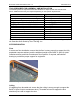
BTS Aisle Containment Manual, Rev. 1.0 ___ December 2013 CREATE THE DUCT 1. Assemble Extrusions to make the two long sections for the bottom of the duct. If cabinet row length is greater than 94” (2387 mm), join extrusions together using the Joiner Gusset and (4) Screws as shown below. Note: • The flat side of the extrusion faces the inside of the containment/duct (see page 8). • The Joiner Gusset faces the outside of the containment/duct.
BTS Aisle Containment Manual, Rev. 1.0 ___ December 2013 2. Cut the extrusions to match the Cabinet Row Length. If cabinet row lengths are uneven, cut Extrusions to match the longest row length. Consider the addition of future cabinets also. Open space at the end of the row can be filled with a Full Height Blanking Panel (sold separately, see page 26).
BTS Aisle Containment Manual, Rev. 1.0 ___ December 2013 3. Use Mounting Brackets to attach extrusions to the ceiling or to the tops of cabinets. • Position the extrusions so Gusset Joiners face the outside of the containment/duct. • Mounting brackets attach to the outside of the containment/duct. • Support extrusions on both sides of Joiner Gussets and close to the ends of the duct. • Space brackets approximately every 48” (1200 mm) of span.
BTS Aisle Containment Manual, Rev. 1.0 ___ December 2013 4. Cut extrusions to cap the ends of the duct and attach with Plate Gussets as shown below. Note the orientation of the Extrusion; the Plate Gusset goes inside the duct. The flat side of the Extrusion faces the inside of the containment. The curves face the outside of the containment/duct. 5. Attach the extrusions to the ends of the duct with the Plate Gussets. Note the orientation of the Extrusion; the Plate Gusset goes inside the duct.
BTS Aisle Containment Manual, Rev. 1.0 ___ December 2013 6. Cut two vertical extrusions per corner. Each vertical extrusion should be 3.25” (83 mm) less than the cabinet to ceiling distance to allow space for the top of the duct frame. Attach the extrusions in the corners with Plate Gussets as shown below. • After the duct frame is complete, you will attach Corner Covers around the outside of the corner extrusions.
BTS Aisle Containment Manual, Rev. 1.0 ___ December 2013 7. Add vertical extrusions every 48” (1200 mm) or at a smaller even interval across the length of the duct. Use two gussets with two screws each to secure each vertical extrusion as shown below. The flat side of the extrusion faces the inside of the duct. This view is from the outside of the containment/duct. The flat side of the extrusions face the inside of the duct/containiment.
BTS Aisle Containment Manual, Rev. 1.0 ___ December 2013 8. Add cross extrusions at every other vertical extrusion. Use three gussets with two screws each to secure each cross extrusion as shown below. This view is from the inside of the containment/duct. Note the flat sides of the extrusion are on the inside of the duct. These edges support the polycarbonate panels.
BTS Aisle Containment Manual, Rev. 1.0 ___ December 2013 9. Repeat the previous steps to cut and assemble a top frame for the duct. Attach cross extrusions at the top also.The top frame of the duct touches the drop ceiling. • The flat side of the extrusion should face the inside of the containment/duct. • Use two plate gussets with two screws each at each corner. • Use two plate gussets with two screws each at each vertical extrusion.
BTS Aisle Containment Manual, Rev. 1.0 ___ December 2013 10. Cut and add Corner Covers around the outside of each corner. See step 6, page 15.
BTS Aisle Containment Manual, Rev. 1.0 ___ December 2013 11. Cut Polycarbonate Panels to fit the duct and secure with Panel Clamps. • The inside of the extrusion used to contstruct the duct has a flat surface with a raised edge that forms a frame for each polycarbonate panel, see the details below. • Measure and cut the polycarbonate panels using a utility knife and straight edge or Guardian Knife Guide and Coroclaw Flute Cutter.
BTS Aisle Containment Manual, Rev. 1.0 ___ December 2013 CREATE DROP PANELS Create drop panels to fill any gaps between the tops of cabinets and the duct. • Drop panels are made with Polycarbonate Panel, Panel Clips and Universal Bulb Seal • Universal Bulb Seal (P/N 33003-001) must be ordered separately. • Order additional panel and clips, if required. • Panels are cut to fit the gap above each cabinet. • Universal Bulb Seal attaches around the edge of the panels. • See the next page for details.
BTS Aisle Containment Manual, Rev. 1.0 ___ December 2013 1. Cut panels and bulb seal, as shown below. 2. Assemble panels and install with clips.
BTS Aisle Containment Manual, Rev. 1.0 ___ December 2013 3. When drop panels are adjacent, interlock the edges of the Universal Bulb Seal.
BTS Aisle Containment Manual, Rev. 1.0 ___ December 2013 CREATE AN END FACIA OVER THE DOOR Aisle Containment Doors must be supported at the top and bottom. The bottom of the doors attach to the floor. The top of the doors must either attach to the tops of the cabinets or to the duct, as shown in the image below. Details for assembling and installing the doors, including details for attaching the doors to the tops of cabinets, are in the next section of this manual.
BTS Aisle Containment Manual, Rev. 1.0 ___ December 2013 1. Cut and assemble the extrusion as shown above with flat sides aligned to form an end fascia. 2. Install the fascia as shown to the left so that the flat side faces the inside of the contained aisle. 3. Measure and cut a Polycarbonate Panel to fit the fascia frame and install with Panel Clips. 4. Attach the door to the bottom of the end fascia with several Mounting Brackets.
BTS Aisle Containment Manual, Rev. 1.0 ___ December 2013 FULL HEIGHT CABINET BLANKING PANELS INTRODUCTION The Full Height Cabinet Blanking Panel (P/N 33002-XXX) is an optional accessory that is used with Build To Spec Kit to fill gaps between cabinets when cabinets are omitted. COMPONENTS The components required for each Full Height Cabinet Blanking Panel are illustrated below. Kits are sold in 2 packs and 10 packs.
BTS Aisle Containment Manual, Rev. 1.0 ___ December 2013 INSTALLATION 1. Measure, cut and assemble the sides of the Full Height Cabinet Blanking Panel. • Measure the height of the opening – the distance from the floor to the bottom of the duct. • Cut the Extrusions and the Universal Bulb Seal to match the height of the opening. • Slide the Universal Bulb Seal onto the Extrusion as shown to the left.
BTS Aisle Containment Manual, Rev. 1.0 ___ December 2013 2. Measure, cut and assemble the Polycarbonate Panel • Measure the width of the opening – the distance between cabinets. • Cut the Polycarbonate Panel to match the width of the opening. • Then, cut the Polycarbonate panel to be 1” (25 mm) higher than the height of the opening. • Insert the trimmed panel into the Universal Bulb Seal so that the panel extends above the tops of the extrusions.
BTS Aisle Containment Manual, Rev. 1.0 ___ December 2013 3. Add Full Height Cabinet Blanking Panels to fill gaps between cabinets and at the ends of rows. Note that the panel is placed on the inside of the containment/duct.
BTS Aisle Containment Manual, Rev. 1.0 ___ December 2013 AISLE CONTAINMENT DOOR SYSTEM INTRODUCTION The Aisle Containment Door Systems from Chatsworth Products, Inc. (CPI) have been developed to meet a wide range of application needs. The door systems can be installed in aisle widths that are between two and three tiles wide. The door systems are designed to be compatible with F-Series TeraFrame® and GF-Series GlobalFrame® cabinets that are between 42U minimum and 52U maximum height (77.8” – 98.9”).
BTS Aisle Containment Manual, Rev. 1.0 ___ December 2013 INSTALLATION The Aisle Containment Door is bolted to the floor and supported to the top of TeraFrame or GlobalFrame cabinets. FLOOR PREPARATION SLAB FLOOR Install four concrete anchors, two for each side panel, using the floor drilling template to accurately locate the holes. The template is not included with the door; it must be ordered separately, 32875-701 for the double door or 32875-702 for the single door.
BTS Aisle Containment Manual, Rev. 1.0 ___ December 2013 SINGLE DOOR For the single door, position the template (PN 32875-702) with the flanges down and oriented for left or right door opening as shown in the pictures shown below; the first picture shows a left opening door and the second shows a right opening door. The side flange should butt against the cabinet side and the template slots should be centered on the aisle.
BTS Aisle Containment Manual, Rev. 1.0 ___ December 2013 ACCESS FLOOR For access floor installations, a door standoff kit (PN 32870-X01 for the double door or PN 32870-X02 for the single right door) is required. The standoff moves the door assembly away from the cabinet by 2.5” so that there is enough clearance for the floor mounting hardware.
BTS Aisle Containment Manual, Rev. 1.0 ___ December 2013 FLOOR MOUNTING ANGLE INSTALLATION SLAB FLOOR Install four 3/8” concrete anchors (PN: 40604-001, not included) into the four drilled holes. Bolt the two mounting angles to the floor with 3/8” hex bolts (not included). ACCESS FLOOR Bolt the two mounting angles to the floor tile with 3/8” hex bolts and fender washers (not included). If subfloor bracing is being used, extend 3/8” threaded rod through the floor tile to the subfloor (not included).
BTS Aisle Containment Manual, Rev. 1.0 ___ December 2013 DOOR FRAME ASSEMBLY REMOVING THE RAIL COVER Lay the rail assembly on the floor; use packaging to protect finish. Remove the four nuts that hold the cover on the rail and remove the cover. Set the cover aside. ASSEMBLING THE DOOR FRAME Position the rail assembly with the front towards the floor. Attach the side panels to the rail assembly using M6 flange nuts (see first picture on following page).
BTS Aisle Containment Manual, Rev. 1.
BTS Aisle Containment Manual, Rev. 1.0 ___ December 2013 Single Door Assemblies shown below – note position of large and small panels.
BTS Aisle Containment Manual, Rev. 1.0 ___ December 2013 STANDOFF ASSEMBLY For access floor installations, a door standoff kit (PN 32870-X01 for the double door, PN 32871-X01 for the single left door, or PN 32871-X02 for the single right door) is required. The standoff is mounted to the frame assembly as shown below. Attach the two side standoffs to the side panels using six M6 pan head screws on each standoff.
BTS Aisle Containment Manual, Rev. 1.0 ___ December 2013 APPLYING PANEL GASKET Apply the adhesive foam gasket to the side panels as shown below. The top gasket should be positioned 2” – 3” (51 – 76 mm) below the top edge of the cabinet. If the cabinet is taller than the door assembly apply the top gasket at the very top of the panels.
BTS Aisle Containment Manual, Rev. 1.0 ___ December 2013 DOOR FRAME INSTALLATION CABINET TOP ATTACHMENT A Cabinet-to-Door Bracket Kit is required to attach the door frame to the top of the cabinets (not included with door). The brackets will work with F-Series TeraFrame and GF-Series GlobalFrame cabinet heights from 42U to 52U. Order one kit per door assembly as follows: For doors without standoff kit: 32805-X00 For top of cabinet heights from 85.3” up to 91.
BTS Aisle Containment Manual, Rev. 1.0 ___ December 2013 BRACKET ASSEMBLY The top mounting brackets can be assembled in two different configurations; the first picture below shows the bracket assembled for the minimum height adjustment and the second shows it assembled for the maximum adjustment. Assemble the two brackets together using two M6 bolts, washers, and nuts for each bracket assembly.
BTS Aisle Containment Manual, Rev. 1.0 ___ December 2013 TERAFRAME AND GLOBALFRAME GEN 2 MOUNTING For F-Series TeraFrame and GF-Series GlobalFrame Gen 2 Cabinets that are taller than the door frame assembly, mount the bracket assembly as shown below. Install the M8 dropin nut in the cabinet’s upper frame slot. Attach the top bracket to the cabinet with the M8x12 bolt and M8 washer into the drop-in nut.
BTS Aisle Containment Manual, Rev. 1.0 ___ December 2013 For F-Series TeraFrame and GF-Series GlobalFrame Gen 2 Cabinets that are shorter than the door frame assembly, mount the bracket assembly as shown below; the picture is shown from the back side of the door. Install the M8 drop-in nut in the cabinet’s upper frame slot. Attach the bracket to the cabinet with the M8x12 bolt and M8 washer into the drop-in nut.
BTS Aisle Containment Manual, Rev. 1.0 ___ December 2013 GF-SERIES GLOBALFRAME GEN 1 MOUNTING Install the Rail Support Bracket kit, PN 32771-X01, on the inside of the GF-Series GlobalFrame Gen 1 Cabinet as shown below. Insert the slide clamp into the cabinet horizontal slide and rotate it to a vertical position. Remove the plastic hole plug from the top panel adjacent to the cable pass port.
BTS Aisle Containment Manual, Rev. 1.0 ___ December 2013 For GF-Series GlobalFrame Gen 1 Cabinets that are taller than the door frame assembly, mount the bracket assembly as shown below. Attach the top bracket to the cabinet with the M8 nut, from the Rail Support Bracket kit, onto the stud. The bottom bracket is attached to the door top rail using one of the pre-installed M6 bolts in the rail and a M6 nut and washer. Attach the bracket cover to the bottom bracket with two M4x6 screws.
BTS Aisle Containment Manual, Rev. 1.0 ___ December 2013 POSITIONING THE DOOR Position the door frame assembly with the bottom of the side panels aligned with the floor mounting angles. Tip the frame assembly up so that the inside pocket of the side panels fit over the floor mounting angles. Utilize a level to ensure the door assembly is vertrically plumb. Check plumbness at the left and right hand side panel assemblies. Tighten the door support bracket hardware.
BTS Aisle Containment Manual, Rev. 1.0 ___ December 2013 CABINET FLOOR ATTACHMENT Attach the bottom of each side panel to the floor mounting angle with three M6 flat head screws and a washer plate. **TIP** Use a flat screwdriver positioned underneath the side panel to aid with hole alignment. LOWER ROLLER INSTALLATION Install the lower roller assemblies (two for the double door and one for the single door) as shown on the following page.
BTS Aisle Containment Manual, Rev. 1.0 ___ December 2013 DOOR INSTALLATION MOUNTING THE DOOR Hang each door panel onto the roller bracket studs and secure with two M8 nuts; the nuts should only be finger tight to allow height and leveling adjustment. Be sure that the rear flange of the door hanger bracket is positioned on top of the leveling nuts, see second picture below. Adjust leveling nuts as required to level each door assembly.
BTS Aisle Containment Manual, Rev. 1.0 ___ December 2013 ADJUSTING LOWER ROLLERS From inside of the door, loosen the lower roller bolts and slide the roller assembly down so that the rear door flange is captured between the two rollers. Adjust the height to maintain at least a 1/4 “ gap between the door flange top and the metal bracket for smooth operation. Tighten the bolts.
BTS Aisle Containment Manual, Rev. 1.0 ___ December 2013 ADJUSTING DOOR ALIGNMENT Q: What if there is an uneven gap between the two door assemblies? A: Either one of both of the door assemblies is not level. Adjust the leveling nuts to level the doors and eliminate the gap. Q: What if the door vertical gasket stops before sealing to the vertical L shaped bracket on the side assemblies? A: The door(s) are not centered on the track. Loosen hardware securing door support brackets to the trolley system.
BTS Aisle Containment Manual, Rev. 1.0 ___ December 2013 AISLE CONTAINMENT FLOOR SEAL KITS INTRODUCTION Aisle Containment Floor Seal Kits are used around the bottoms of the cabinets to seal the gaps between the floor and the bottoms of the cabinets. A cabinet-specific kit is available for CPI F-Series TeraFrame, GF-Series GlobalFrame and N-Series TeraFrame Network Cabinets.
BTS Aisle Containment Manual, Rev. 1.0 ___ December 2013 FOR F-SERIES TERAFAME GEN 2 CABINET 1. Install bottom seals on front and rear of each cabinet as shown. 2. Install side bottom seal on end row cabinets.
BTS Aisle Containment Manual, Rev. 1.0 ___ December 2013 SIDE BOTTOM SEAL RUBBER SEAL M4X12 SCREW FOR ALL OTHER CABINETS 1. Check with the cabinet’s manufacturer for a cabinet-specific kit 2. If not available, use the AisleLok Under Rack Panel (CPI P/N 13877-XXX) or AisleLok Acrycell Sealing Tape (CPI P/N 13876-XXX) to seal the gaps under the cabinets.
BTS Aisle Containment Manual, Rev. 1.0 ___ December 2013 ACCESSORIES For Build To Spec Kit and Full Height Cabinet Blanking Panel.
BTS Aisle Containment Manual, Rev. 1.