
Manual


Remote Infrastructure Management System - Version 1.0 / July 2014
Chatsworth Products, Inc. (CPI) • 800-834-4969 19
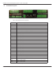
1.5. Rear Panel Indicators
The rear panel of the RIM-1000 houses a series of green LEDs.
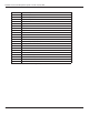
The chart below tracks indicator status when the
corresponding green LED is illuminated:
Figure 1.3 Rear Panel Indicators
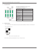
1.6. SW1 Switch Settings
• SW1-1: EIA-485 Termination switch should be in the down position (ON) if the RIM-1000 is an end device on an EIA-485 network.
• SW1-2: Reserved for future use.
Figure 1.4 SW1-1 Switch and SW1-2 Switch
SW1-1 switch is in the down position (ON) and SW1-2 switch is in the up position (OFF).
Status Indicator
K1 (Output Relay) Relay is energized.
EIA-232 TX (COM2)
Interface
Data is being transmitted
EIA-232 or EIA-485 TX
(COM 1) Interface
Data is being transmitted
EIA-232 (COM 1) Select
Interface
EIA-232 selected (P2)
K2 (Output Relay)
Relay is energized.
EIA-232 RX (COM 2)
Interface
Data is being received
EIA-232 or EIA-485 RX
(COM 1) Interface
Data is being received
EIA-485 (COM 1) Select
Interface
EIA-485 selected (TB5)