
Manual

Remote Infrastructure Management System - Version 1.0 / July 2014
30 www.chatsworth.com
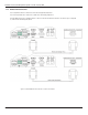
2.2.10 Expansion Card A Connections
A sticker identifying the expansion cards as A or C is located on each Expansion Card. The following wiring diagrams show the
Expansion Card in slot 1. However, the Expansion Card may be in Slot 2, 3 or 4 based on the RIM-1000 configuration. The I/O for each
card type appears on the back of the RIM-1000 for reference during field wiring; see Figure 2.12 through Figure 2.16 for typical wiring.
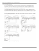
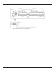
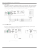
Expansion Card A has 12 non-isolated analog input channels and 8 relay output channels. The analog input channels can be wired
for 4-20ma, 0-5vdc, 0-10VDC, NO (normally open) dry contact or NC (normally closed) dry contact. The circuit board has internal jumpers
to select an ma input or a voltage input. The factory default is set as a 4-20ma input. See Appendix A, “RIM-1000 Expansion Cards” on
page 169, for jumper location and settings.
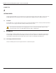
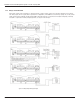
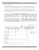
Figure 2.12 I/O Terminals for Expansion Card A
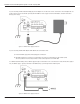
Figure 2.13 Analog Input Wiring for Expansion Card A