Remote Infrastructure Management (RIM-600) User Manual Version 1.04 800-834-4969 techsupport@chatsworth.com www.chatsworth.com ©2006 Chatsworth Products, Inc. All rights reserved. CPI and MegaFrame are registered trademarks and TeraFrame is a trademark of Chatsworth Products, Inc. All other trademarks belong to their respective companies.
Every effort has been made to ensure that the information in this document is complete, accurate and up-to-date. Chatsworth Products, Inc. assumes no responsibility for the results of errors beyond its control. Chatsworth Products, Inc. also cannot guarantee that changes in equipment made by other manufacturers, and referred to in this manual, will not affect the applicability of the information in this manual. Copyright © 2006 by Chatsworth Products, Inc. First Edition, version 1.
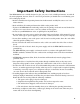
Important Safety Instructions Your RIM-600 has been carefully designed to give you years of safe, reliable performance. As with all electrical equipment, however, there are a few basic precautions you should take to avoid hurting yourself or damaging the unit: • Read the installation and operating instructions in this manual carefully. Be sure to save it for future reference. • Read and follow all warning and instruction labels on the product itself.
RIM-600 Manual • To reduce the risk of fire or injury to persons, read and follow these instructions: 1. Use only the specified type and size batteries. 2. Do not dispose of the batteries in a fire. The cell may explode. Check with local codes for possible special disposal instructions. 3. Do not open or mutilate batteries. Released electrolyte is corrosive and may cause damage to the eyes or skin. It may be toxic if swallowed. 4.
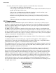
If the equipment is causing harm to the telephone network, the telephone company may ask that you disconnect this equipment from the network until the problem has been corrected or until you are sure that the equipment is not malfunctioning. Part 15: This equipment has been tested and found to comply with the limits for a Class A digital device, pursuant to Part 15 of the FCC Rules.
RIM-600 Manual Users should ensure for their own protection that the electrical ground connections of the power utility, telephone lines and internal metallic water pipe system, if present, are connected together. This precaution may be particularly important in rural areas. CAUTION: Users should not attempt to make such connections themselves, but should contact the appropriate electric inspection authority, or electrician, as appropriate.
1 YEAR LIMITED WARRANTY PLEASE READ THIS WARRANTY CAREFULLY BEFORE USING THE PRODUCT. THIS LIMITED WARRANTY CONTAINS CHATSWORTH PRODUCTS’ STANDARD TERMS AND CONDITIONS. WHERE PERMITTED BY THE APPLICABLE LAW, BY KEEPING YOUR CHATSWORTH PRODUCT BEYOND THIRTY (30) DAYS AFTER THE DATE OF DELIVERY, YOU FULLY ACCEPT THE TERMS AND CONDITIONS SET FORTH IN THIS LIMITED WARRANTY.
RIM-600 Manual YOU AGREE TO RELEASE, WAIVE, DISCHARGE AND COVENANT NOT TO SUE WARRANTORS, THEIR OWNERS, DIRECTORS, OFFICERS, EMPLOYEES, AGENTS, SUPPLIERS OR AFFILIATED COMPANIES, FOR ANY AND ALL LIABILITIES POTENTIALLY ARISING FROM ANY CLAIM, DEMAND OR ACTION BASED UPON ANY LOSSES, LIABILITIES, DAMAGES OR COSTS, INCLUDING BUT NOT LIMITED TO DAMAGES THAT ARE DIRECT OR INDIRECT, INCIDENTAL, SPECIAL OR CONSEQUENTIAL, AND INCLUDING ATTORNEYS FEES AND LEGAL COSTS, THAT MAY RESULT FROM THE INSTALLATION, OPERATION
Table of Contents Table of Contents Important Safety Instructions . . . . . . . . . . . . . . . . . . . . . . . . . . . . . . . . . . . . . . . . . . . . . . iii FCC Requirements. . . . . . . . . . . . . . . . . . . . . . . . . . . . . . . . . . . . . . . . . . . . . . . . . . . . . . . iv Telephone Consumer Protection Act (Host only) . . . . . . . . . . . . . . . . . . . . . . . . . . . . . . . . .v General Requirements for all Automatic Dialers (Host only). . . . . . . . . . . . . . . . . . . . . . . . .
RIM-600 Manual RIM-600 Host Specifications . . . . . . . . . . . . . . . . . . . . . . . . . . . . . . . . . . . . . . . . . . . . . Operating Specifications . . . . . . . . . . . . . . . . . . . . . . . . . . . . . . . . . . . . . . . . . . . . . . . . Communications Specifications . . . . . . . . . . . . . . . . . . . . . . . . . . . . . . . . . . . . . . . . . . Environmental Monitoring . . . . . . . . . . . . . . . . . . . . . . . . . . . . . . . . . . . . . . . . . . . . . .
Table of Contents Record and Assign Voice Messages. . . . . . . . . . . . . . . . . . . . . . . . . . . . . . . . . . . . . . . . Software Installation and Hardware Requirements . . . . . . . . . . . . . . . . . . . . . . . . . . . Hardware and Software Requirements. . . . . . . . . . . . . . . . . . . . . . . . . . . . . . . . . . . . . Minimum Requirements: . . . . . . . . . . . . . . . . . . . . . . . . . . . . . . . . . . . . . . . . . . . . . . Software Installation . . . . . . . . . . . . . . . . . .
RIM-600 Manual Configuring User Profiles and Contacts . . . . . . . . . . . . . . . . . . . . . . . . . . . . . . . . . . . . Configuring User Profiles . . . . . . . . . . . . . . . . . . . . . . . . . . . . . . . . . . . . . . . . . . . . . . . Adding a Profile. . . . . . . . . . . . . . . . . . . . . . . . . . . . . . . . . . . . . . . . . . . . . . . . . . . . . . . Permissions. . . . . . . . . . . . . . . . . . . . . . . . . . . . . . . . . . . . . . . . . . . . . . . . . . . . . . . . . . Classes . .
Table of Contents Graphs . . . . . . . . . . . . . . . . . . . . . . . . . . . . . . . . . . . . . . . . . . . . . . . . . . . . . . . . . . . . . . Updating the Web Page . . . . . . . . . . . . . . . . . . . . . . . . . . . . . . . . . . . . . . . . . . . . . . . . Viewing the Remote Web Page . . . . . . . . . . . . . . . . . . . . . . . . . . . . . . . . . . . . . . . . . History . . . . . . . . . . . . . . . . . . . . . . . . . . . . . . . . . . . . . . . . . . . . . . . . . . . . . . . . . . . . . .
RIM-600 Manual Chapter 5: PowerGate . . . . . . . . . . . . . . . . . . . . . . . . . . . . . . . . . . . . . . . . . 93 Physical Description. . . . . . . . . . . . . . . . . . . . . . . . . . . . . . . . . . . . . . . . . . . . . . . . . . . . Front Panel Layout . . . . . . . . . . . . . . . . . . . . . . . . . . . . . . . . . . . . . . . . . . . . . . . . . . . Rear Panel . . . . . . . . . . . . . . . . . . . . . . . . . . . . . . . . . . . . . . . . . . . . . . . . . . . . . . . . . . LEDs . . . . . . .
Table of Contents RIM-600 PowerGate2 Specifications . . . . . . . . . . . . . . . . . . . . . . . . . . . . . . . . . . . . . . 105 Chapter 7: RIM-600 Sensors . . . . . . . . . . . . . . . . . . . . . . . . . . . . . . . . . . . 107 60010-001 Room Temperature Sensor . . . . . . . . . . . . . . . . . . . . . . . . . . . . . . . . . . . . Installation Instructions. . . . . . . . . . . . . . . . . . . . . . . . . . . . . . . . . . . . . . . . . . . . . . . . Introduction . . . . . . . . . . . . . . . . . . .
RIM-600 Manual Electrical box installation . . . . . . . . . . . . . . . . . . . . . . . . . . . . . . . . . . . . . . . . . . . . . Hidden cable surface installation . . . . . . . . . . . . . . . . . . . . . . . . . . . . . . . . . . . . . . . Visible cable surface installation . . . . . . . . . . . . . . . . . . . . . . . . . . . . . . . . . . . . . . . . Configuration . . . . . . . . . . . . . . . . . . . . . . . . . . . . . . . . . . . . . . . . . . . . . . . . . . . . . . .
Table of Contents Introduction . . . . . . . . . . . . . . . . . . . . . . . . . . . . . . . . . . . . . . . . . . . . . . . . . . . . . . . . Package Contents. . . . . . . . . . . . . . . . . . . . . . . . . . . . . . . . . . . . . . . . . . . . . . . . . . . Cabling . . . . . . . . . . . . . . . . . . . . . . . . . . . . . . . . . . . . . . . . . . . . . . . . . . . . . . . . . . . Mounting . . . . . . . . . . . . . . . . . . . . . . . . . . . . . . . . . . . . . . . . . . . . . . . . . . . . . . . . . .
RIM-600 Manual Package Contents. . . . . . . . . . . . . . . . . . . . . . . . . . . . . . . . . . . . . . . . . . . . . . . . . . . . Configuration . . . . . . . . . . . . . . . . . . . . . . . . . . . . . . . . . . . . . . . . . . . . . . . . . . . . . . . Sensitivity Adjustment . . . . . . . . . . . . . . . . . . . . . . . . . . . . . . . . . . . . . . . . . . . . . . . . Sensor Template (factory default) . . . . . . . . . . . . . . . . . . . . . . . . . . . . . . . . . . . . . . . . Specifications . .
Chapter 1: Installation Chapter 1: Installation Introduction Congratulations on your purchase of the Chatsworth RIM-600 Remote Infrastructure Management System. This one-of-a-kind solution will change the way you think about computer room and network monitoring. The system is designed to be a comprehensive method of ensuring 100% up-time of your computer systems.
RIM-600 Manual About This Manual This manual comprises the instructions and commands necessary to install and program the RIM600. Additional summary and application chapters are included to help you speed programming and to understand RIM-600’s features. You should thoroughly read this manual to establish a basic understanding of the system and keep it as a reference. HOST INSTALLATION and CONFIGURATION Physical Description The RIM-600 Host is housed in a 17”w x 1.
Chapter 1: Installation Certain private telephone systems and public switching equipment may not accept the unit’s dialing or may generate an unacceptable ring signal. In those cases, a dedicated line may be required for the unit. Consult the supplier of your telephone system if you encounter problems. CAUTION: Never install telephone wiring during a lightning storm. Never install telephone jacks in wet locations unless the jack is specifically designed for wet locations.
RIM-600 Manual AC Power and Battery LEDs The AC Power and Battery alarm status is indicated by two red LEDs. Their modes of operation are described below. Mode 1: No Alarm LED: OFF Mode 2: Alarm detected but has not exceeded recognition time LED: FAST BLINK Mode 3: New Alarm exists and not yet acknowledged LED: SLOW BLINK Mode 4: Alarm has been acknowledged but input is still out of range LED: ON Microphone Jack The Host unit comes with a built-in microphone.
Chapter 1: Installation Operating Environment Before you install the RIM-600 Host be sure that your operating environment meets the physical requirements of the equipment. Operating Temperature: Humidity: Power: Rack Requirements: Tabletop requirements: 32º–122º Fahrenheit (0º– 50º C) 5– 90 %RH, non-condensing 90–260VAC 47/63 Hz outlet within 6' Standard 19" equipment rack with supplied mounting bracket hardware. Requires 1.0 EIA rack mount space.
RIM-600 Manual Figure 4: Wall-mounted Host Unit Tabletop Installation The RIM-600 Host can be installed on a tabletop or shelf. Follow the steps below: 1) Attach the four self-adhesive rubber feet to the four corners on the bottom of the RIM-600. 2) Place the unit on a tabletop or shelf and connect the power cord into a 90-260VAC outlet.
Chapter 1: Installation Another benefit of using RJ-45 connectors is that you can easily locate sensors at distant locations within your facility by using your existing structured cabling. For example: Suppose you have an RIM-600 installed in room A and you want to install a sensor in room B.
RIM-600 Manual Enterprise Status Unit RIM-600 Monitor NY_Node Type IP Host 10.1.4.10 Node 10.1.4.17 Status Ok Ok Press any key to return to main menu Option 2 will display the network configuration for the Host as well as web server, RAS, and twoway email settings. A sample of Option 2 is shown below: Network and Option Configuration Physical Address 00:D0:C9:37:40:86 IP Address 10.1.4.10 Subnet Mask 255.255.255.0 Default Gateway 10.1.4.1 DNS Server 10.1.2.
Chapter 1: Installation 5. Return to main menu Option 6 allows you to configure the RAS (Remote Access Server). This can be used to provide remote access to your network via a dial-up connection to the RIM-600 Host. Note that there are serious security risks associated with enabling this feature. A sample of the RAS menu is shown below: Configure Remote Access Server 1. Enable/Disable RAS Support 2. RAS IP address 3.
RIM-600 Manual Option B allows you to change the Local Configuration password. Option C allows you to reset all settings to their default values. Option D will display statistics. Option E will save all changes and reboot the system. A reboot is required for changes to take effect. Option F will save all changes and logout, but the changes will not be activated until the system reboots.
Chapter 1: Installation Battery Maintenance The RIM-600 Host includes an internal UPS that automatically switches to battery backup in the event of an AC power failure. The battery in the RIM-600 Host is a 12V 2.9AH gel cell. This battery will keep the unit operating for approximately 3.5 hours when fully charged and under normal operating conditions. Service life Over time and with periodic use, the battery will begin to lose its capacity, resulting in less overall backup time.
RIM-600 Manual 30 Step 5) Remove all of the screws in the top cover. Carefully remove the top cover. Step 6) Locate the battery on the right side. There will be a red wire (positive) and a black wire (negative) connected to the battery. Using needle nose pliers, remove the connector with the black wire from the battery first. Gently wiggle it off. Step 7) Using needle nose pliers, remove the connector with the red wire from the battery.
Chapter 1: Installation Host Specifications RIM-600 Host Specifications Operating Specifications Temperature Humidity Power Supply Power Consumption (typ) Power Connection Dimensions Backup Battery Backup Time 32–122° F 5–90% RH non-condensing 90–260VAC 47–63Hz 25 Watts IEC 320 1.75"h x 9.5"d x 19"w 12V 2.9AH Sealed Gel Cell 3.5 Hours Communications Specifications Ethernet RS-232 Modem Fax Voice Processor 10/100 Base-T, 10/100Mbps DB9, 9600bps, DTE 33.6Kbps Group 3, 14.
RIM-600 Manual NODE INSTALLATION & CONFIGURATION Physical Description The RIM-600 Node is housed in a 9.6"w x 1.75"h x 7"d enclosure, which is 1 EIA rack-mount space high. Front Panel Layout The front panel contains connections for eight sensor inputs, microphone input, Ethernet port, serial port, and power LED.
Chapter 1: Installation ON/OFF Switch The on/off switch connects main power and battery power to the system. In the event that main power fails, the backup battery system will automatically power the system. Rear Panel The rear panel is where the main power cord exits the unit. A 120VAC/60Hz to 8VAC adapter provides main power to the unit. Battery Compartment The battery compartment is located below the top panel. The unit requires (1) 6V 3.4AH rechargeable battery (included).
RIM-600 Manual Battery Replacement The RIM-600 Node uses one (1) 6V 3.4AH rechargeable battery (included) for backup power in the event that main power fails. The unit will constantly recharge the battery whenever the power switch is turned on and the unit is plugged into a power supply. In the event you need to replace the battery, contact technical support for part number information. To install the new battery, first slide the power switch to the OFF position and disconnect the power adapter.
Chapter 1: Installation NOTE: An international version is available for 220V/50Hz operation. (Order part # 60001-002.) Figure 10: Wall-mounted Node Unit Tabletop Installation The RIM-600 Node can be installed on a tabletop or shelf. Follow the steps below: 1) Attach the four self-adhesive rubber feet to the four corners on the bottom of the RIM-600. 2) Place the unit on a tabletop or shelf and connect the power cord into a 120VAC 60Hz outlet.
RIM-600 Manual an RJ-45 interconnect cable to connect the RIM-600 Node to the patch panel in room A, and an RJ45 interconnect cable from the wall jack in room B to the sensor. The sensor produces an analog signal which must connect directly to the Host or Node. The path from the sensor to the RIM-600 unit CANNOT pass through a network Hub or Switch. Network Configuration The RIM-600 Node has a serial port on the front panel which is used to configure network settings and security options.
Chapter 1: Installation NOTE: You can remotely reconfigure the Node network settings using the RIM-600 ConsoleView software if the Allow Remote Configuration option is set to Y. However, the Node must initially be configured via the serial port before any remote configuration is possible. Option 3 will display operating statistics of the Node. This information may be useful for troubleshooting.
RIM-600 Manual Node Specifications Operating Specifications Temperature Humidity Power Supply Power Consumption Dimensions 32–122° F 5–90% RH non-condensing 120VAC 60Hz 10 Watts 1.8"h x 7.0"d x 9.6"w Backup Battery (1) 6V 3.4AH sealed rechargeable Backup Time 3.
Chapter 2: Software Chapter 2: RIM-600 Software Introduction This chapter is designed to help you program and use the RIM-600 to its fullest potential. The RIM-600 system helps you maintain, monitor, expedite and control the things that affect your information infrastructure. Help The RIM-600 ConsoleView Software provides an extensive Help system to supplement the documentation. Use RIM-600 Help to access information about commands and dialog boxes.
RIM-600 Manual Note: Do not save the default username and password, because it will be deleted automatically once a Master System Administrator profile is configured. Configure the Unit Properties for the Host and Node(s) Right-click on the word Host and select Unit Properties. Step through each tabbed page and enter the relevant information for your application. The Numeric Unit ID should be set to the Host's telephone number. Most Alphanumeric pagers work best when set to 1200bps.
Chapter 2: Software Configure User Profiles and Contacts Program the User Profiles and Contacts to control who has access to the RIM-600 and who gets contacted when an alarm occurs. Each user must have a Username, Password, and User Code. Right-click on Profiles and select Add New Profile. Enter information for each user. Click the Permissions button and be sure to set up at least one Master System Administrator account.
RIM-600 Manual RIM-600 Host Identification message - Host Unit Properties Screen RIM-600 Node Identification message - Node Unit Properties Screen Input Sensor message - Input Channel Setup Screen IP Alarms message - IP Alarm Setup Screen PowerGate messages - PowerGate Setup Screen Software Installation and Hardware Requirements This section describes how to install and configure the RIM-600 ConsoleView Software for your enterprise.
Chapter 2: Software Figure 5: Installation screen Starting the RIM-600 ConsoleView Software Double-click the RIM-600 icon to start the RIM-600 ConsoleView Software. The software will automatically try to connect to all RIM-600 Hosts that have been configured. If this is the first time you are running the software, you will need to create an Enterprise Group and add a Host within each Enterprise.
RIM-600 Manual Adding an Enterprise Group From the ConsoleView menu, click on Enterprise and select Add Enterprise Group. In the left-hand column, a New Enterprise Group will appear. When you connect to the host, the Enterprise Name will update. Deleting an Enterprise Group If at any time you wish to delete an Enterprise group, click to highlight the Enterprise Group you would like to delete, select Enterprise from the main menu and choose Delete Enterprise Group.
Chapter 2: Software Setting the Unit Properties for the RIM-600 Host To set the global properties of your RIM-600, right-click on the Host name and select Unit Properties. On the System Info tab, enter the Unit Name, Description and Location. These parameters will be used when sending alarms to identify the unit. Check the Auto-Connect on Startup box if you want the RIM-600 software to connect automatically with the unit at startup. See Figure below.
RIM-600 Manual this value to at least 1 minute. When set to 0 the unit will dial back-to-back calls without the possiblity of calling in to acknowledge an alarm. The Intercall Delay can be set from 0–60 minutes. Test Dial Tone: The RIM-600 can be programmed to test periodically for dialtone to ensure that the telephone line is alive in the event that the unit has to dial out for an alarm.
Chapter 2: Software The Node name will appear in green when host-to-node communications are working properly. If a communications problem occurs, the node name will initially turn yellow, to indicate that pending node trouble exists. If the problem persists for several minutes, the node name will turn red and a trouble alarm will be dispatched to Users who are members of the diagnostic class. Deleting a Node To delete a Node, right-click on the Node name in the tree and select Delete This Node.
RIM-600 Manual In normal operation information is periodically passed between the Node and Host. This information mainly consists of current Input values and IP Alarm status. The amount of data transferred during this update is about 700 bytes. You can choose how often information is updated from the Node by selecting either periodic updates (Auto Send) or by selecting Update on a Percent Change basis. This can be used to control network traffic.
Chapter 2: Software Figure 15: Node Network Settings NOTE: If the Modify button is grey (inactive) then the unit either does not have the Allow Remote Configuration option set, or the unit’s firmware does not support this feature and requires upgrading. Enter the new network parameters and click OK. The Node will reboot and temporarily disconnect from the Host. Configuring Environmental Inputs Each host or node can have up to 8 external sensors connected.
RIM-600 Manual Figure 17: Channel Setup screen Set up the parameters for your environmental input on this screen. Name: Enter a name which describes what the sensor is monitoring. (ex: Mail Server, Data Center Rack #3, …) Type: The sensor type is determined automatically when the sensor is plugged into the host or node. Status: The status indicates if the sensor is presently within alarm limits.
Chapter 2: Software Channel Enabled: This box provides a simple means to enable or disable a sensor channel. Add to Datalog: Click this box to store the value or status of the channel in the datalogger. Value: This is the current value of the sensor connected to the channel (only valid for analog sensor types). Min: This is the minimum value reached by the sensor since it was connected to the unit. Max: This is the maximum value reached by the sensor since it was connected to the unit.
RIM-600 Manual Alarm Response via the PowerGate, PowerGate2, or Camera PowerGate When an alarm occurs, you can have PowerGate or PowerGate2 outlets automatically turn ON, turn OFF, or CYCLE power to a device. Cycling will switch an outlet OFF for 10 seconds and then switch it back ON. To set up a PowerGate, click the Alarm Response button on the Channel Setup Screen. A sample Alarm Response screen is shown below. Figure 21: Alarm Response screen for PowerGate Select Response Type: Choose “PowerGate.
Chapter 2: Software would like the snapshots to be sent. There are two options to determine the Duration over which snapshots will be sent. If you choose While in Alarm you will receive snapshots continuously until the input goes back to normal. If you choose Total you will receive a fixed number of snapshots once the alarm is detected. You can also select the time between snapshots in the Snapshot Interval field, and you can choose the maximum number of Snapshots Sent per E-mail.
RIM-600 Manual Environmental Input Alarm Logic Each environmental input will automatically detect the type of sensor connected (temperature, humidity, power, motion...). Analog sensors will include high and low alarm limit programming options while two-state sensors (Normal/Alarm) will simply have a recognition time. In order for an alarm to be dispatched, the sensor must meet the following criteria: a) It must be Enabled—as configured through the schedule.
Chapter 2: Software configure the Templates, click the plus box next to the word Settings to expand the options under this heading. Next, expand the Input Templates. This will list all of the different sensor types. Figure 24: Template Types Right-click on each of the sensor names to bring up the individual Template programming screens. An example is shown below.
RIM-600 Manual Configuring IP Alarms IP Alarm Setup Each host or node can monitor up to 64 IP addresses through pinging and port availability. In addition, IP dependencies can be programmed to prevent multiple alarm messages from being sent when common network paths are down. Programming Alarm Parameters To program the IP Alarm parameters, expand the Host or Node by clicking the plus box next to the host/node name. Next, expand the IP Alarms.
Chapter 2: Software Schedule: Click this button to bring up the Edit Schedule screen. This screen allows you to set times when the IP Alarm is enabled or disabled. The blue line indicates days/times when the channel is enabled. Figure 27: IP Schedule screen The schedule example above enables the IP alarm 24 hours a day, including holidays. Editing the schedule: • Click on the All button in the top left corner of the grid to enable/disable the entire week.
RIM-600 Manual Alarm Logic Network devices are monitored by the RIM-600 by pinging/connecting to programmed IP addresses about once a minute. The unit will only attempt to ping/connect to devices which are Enabled by the Schedule. Each time the network device responds, the RIM-600 updates the Last Response time. A time limit for responding is assigned to each IP Alarm to determine if the device is functioning properly. This time limit is called the ping Timeout.
Chapter 2: Software Figure 28: IP Alarm Flowchart Removing an IP Alarm Expand the IP Alarms and right-click on the IP Alarm you wish to remove. Choose Delete this IP Alarm, and it will be removed.
RIM-600 Manual Input/Alarm Classes Classes are used to associate environmental inputs and IP alarms with people. Each input sensor or IP address must be assigned to a Class. Each person or User Profile selects classes for which they have responsibility. To view the list of Classes, expand the Settings menu, then right-click on Classes and select Properties. Several classes have been pre-defined in the RIM-600 to give you a starting point.
Chapter 2: Software Configuring User Profiles and Contacts Configuring User Profiles The User Profile section controls who has access to the RIM-600 and who gets contacted when an alarm occurs. The User Profile programming screen describes attributes of the user including: name, title, company, dept, username, password, user code, time zone, classes, etc. When an alarm occurs the RIM-600 will check the list of User Profiles to see who should be contacted.
RIM-600 Manual The “Enable This Profile” option provides a convenient way to temporarily enable or disable a User Profile. When a Profile is disabled (unchecked), no alarms or reports will be sent to that user, and the user will not be permitted to log on to the system. Clicking the Permissions button will bring up the Permission screen. Permissions Each user profile has a programmable security level for each device (host/nodes) in the system. To set the Security Access level click the Permissions button.
Chapter 2: Software Figure 31: Permissions screen To configure profiles for Site Administrator or User security levels, select the appropriate Host or Node(s) and click the arrow to copy the Host/Node(s) into the appropriate list. The double arrow >> will copy all units to the list while the single arrow > will copy just the selected unit to the list.
RIM-600 Manual Figure 32: Class Selection screen Deleting a Profile From the hierarchy on the ConsoleView screen, right-click on the profile you wish to delete and select Delete This Profile in the contextual menu. Contacts The Contacts are the actual telephone numbers, e-mail addresses, pager numbers, etc… that the RIM-600 will contact when an alarm occurs. You can have up to 8 Contacts per User Profile.
Chapter 2: Software Voice Calls For most voice calls you can simply enter the telephone number of the person you want called. Consider the location of the RIM-600 Host when entering the number. If an area code is required to call from the Host to your telephone, be sure to include it. Examples: no area code required: 555-1234 Area code required: (610)-555-1234 1 + area code required: 1-(610)-555-1234 You can also include additional codes within the telephone number.
RIM-600 Manual Fax Calls Enter the telephone number of the fax machine. E-mail Enter the e-mail address. SNMP Enter the SNMP server IP address in numeric form (e.g. 192.168.0.1) Schedule Click the Schedule button to bring up the Schedule screen for this Contact. Choose the times you want the Contact to be enabled by adjusting the blue bars. Areas where the blue bar appears indicates the day and time the Contact is Enabled.
Chapter 2: Software Saving and Loading Programming The programming in your RIM-600 can be saved to a file. This gives you the ability to back up your programming or copy the same programming to another RIM-600 unit. Note that the file you save will not include custom voice files or settings entered through the serial port (network parameters, web settings, two-way e-mail, RAS, etc.). To save your programming to a file, right-click on the name of your host and select Save Programming.
RIM-600 Manual Figure 36: Custom Voice Manager Click on the New button. This will display the MS Windows Sound Recorder program shown below. Figure 37: Sound Recorder screen For the voice messages to play back correctly you must set the recording format to PCM, 8KHz, 8 bit, mono. To set these parameters click File, then Properties. Next, click the Convert Now button. In the Format field select “PCM.” In the Attributes field select “8,000 Hz, 8 Bit, Mono 8 KB/s.” See the following screen.
Chapter 2: Software The window to the right displays all of the voice message file names stored in the RIM-600. To change the file name of a voice message click Rename. Enter a new file name and click OK. To delete a voice message, highlight the message and click the Delete button. To listen to a voice message, highlight the message and click the Listen button. Note: You must have a sound card and speakers/headphones to hear the audio.
RIM-600 Manual Alarm Message Pop-Ups While online with one or more RIM-600 units through the ConsoleView Software, you can have an alarm message pop up on your computer screen whenever an alarm occurs. This could be an environmental or IP alarm on any Host or Node. You can configure this feature to display a general message indicating the Unit and Channel names, or you can associate a custom message with each input. The custom message can be displayed as plain text or HTML.
Chapter 2: Software Setting Pop-Up Text Location When using custom pop-up messages you must specify where these messages will be located. To do this, right-click on the name of your host within the menu tree and select Alarm Pop-Up Notice Location. Select the drive and folder where the messages will be stored. Editing Pop-Up Custom Message To edit the custom message for a particular environmental input or IP alarm, right-click on the chosen input and select Edit Alarm Pop-Up Message.
RIM-600 Manual Figure 45: Alarm Notification screen E-Mail Setup and Two-Way E-Mail Commands The RIM-600 can send alarm messages via e-mail using SMTP as well as respond to commands via e-mail. See the Two-Way E-mail section for more information on sending commands. To set up the e-mail parameters right click on the Host name and select Network Settings.
Chapter 2: Software (g) The unit cannot reach your DNS server and thus cannot look up the SMTP server IP address. (h) The DNS server IP address is programmed incorrectly in the RIM-600 Network Configuration settings. Two Way E-Mail The RIM-600 Host has the ability to send and receive standard pop/smtp e-mail. In addition to using e-mail as a method of delivering outbound alarm messages, e-mail can also be used for remote access into the RIM-600.
RIM-600 Manual Requesting a PowerGate Outlet Command To request a PowerGate Outlet command, send an e-mail message to your RIM-600 Host with the following information: To: Subject: rim600 username: email: command: powergate "" "" on/off/cycle For example: To: rim600@mycompany.com Subject: rim600 username: jsmith email: jsmith555@aardvark.
Chapter 2: Software Configuring a Video Camera The RIM-600 is compatible with the following network cameras.
RIM-600 Manual Up to 128 cameras can be configured in a RIM-600 system. These can be a mix of Axis cameras, Axis camera servers, and Panasonic devices. Once the camera(s) have been configured they can then be associated with a particular Host or Node so that links for these cameras will appear within the menu tree for the chosen unit. You can associate a camera with more than one device if desired. To associate one or more cameras, right-click on Cameras within the menu tree for the selected host or node.
Chapter 2: Software Web Page The RIM-600 will produce a web page which includes: • The status of all Environmental Inputs and IP Alarms. • The ability to program most parameters. • Links to view logged data for each Input and IP alarm. • Links to view historical alarm information for each Input and IP alarm. • Graphs of the last 24 hours of logged data. • The present state of all PowerGate outlets. • Links to Live images from cameras.
RIM-600 Manual The summary will be replaced by a graph for the chosen Environmental/IP item. (See following figure.) Figure 50: Graph of AC Power Updating the Web Page You can enable Automatic Updates of the data and select the interval between updates by rightclicking on the Host and selecting Network Settings. Click on the WebView tab. Check the Automatic Refresh box and enter the number, in seconds, between updates, in the Update Every box.
Chapter 2: Software Figure 52: Web FTP screen Click the Enable FTP Delivery box and fill in the necessary information for your FTP server. Your service provider will have to provide you with the FTP Server name and sub directory where your files will be uploaded. You will also be required to enter your username and password. You can set how often you want the web page to be updated by entering an interval time in the Update box. Enter a file name for the web page (e.g. rim600.html).
RIM-600 Manual computer or a network server. While the program defaults to saving the history database on your local drive, if the system will be used by many users it may be advantageous to store the database on a network drive. To specify the drive for saving History information click File, then Options from the main menu.
Chapter 2: Software Viewing History Datalog History can be viewed through the ConsoleView software or via the RIM-600 web page. It can be viewed through the ConsoleView software in two ways: There is the quick view which can be displayed by right-clicking on an input or profile and selecting History, or you can perform a query on the entire history database using the HistoryView program (right-click on History in the menu tree and select HistoryView, or from the main menu select File, then HistoryView).
RIM-600 Manual If you double-click on an item in the Environmental or IP Alarm box, all of the listed items will become selected and/or deselected. Last, select a time frame to perform the query and click View. The selected data will now be displayed. See sample screen below: Figure 56: History Viewer Graphing Graphing data is possible when the selected query contains only Samples. If you click on the Graph button, all of the points in the query will be displayed as a line graph.
Chapter 2: Software Click on File and select Export Field Names from the submenu if you want the field titles (Date, Time, Event Code, etc.) to be included with the data when you export. Copying to the Clipboard You can highlight and copy selected cells within the grid to the Windows clipboard. To highlight the data simply click-and-hold the left mouse button and drag the mouse over the cells you wish to highlight, then either right-click and select Copy, or click Edit from the main menu and select Copy.
RIM-600 Manual Figure 57: A manual Datalog Download in progress Updating Firmware From time to time Firmware updates will become available to add features or improve the performance of your RIM-600. Most Firmware updates will be included as part of a complete RIM-600 installation upgrade. Check the RIM-600 website (www.chatsworth.com/RIM600) for the latest information on updates. To check the version of Firmware in your RIM-600, right-click on the Hostname and select Version Info.