ART-575W Spectrum™ 575W USER MANUAL CHAUVET, 3000 N 29th Ct, Hollywood, FL 33020 U.S.A (800) 762-1084 – (954) 929-1115 FAX (954) 929-5560 www.chauvetlighting.
TABLE OF CONTENT TABLE OF CONTENT....................................................................................................................................................... 2 BEFORE YOU BEGIN....................................................................................................................................................... 3 WHAT IS INCLUDED ..........................................................................................................................................
BEFORE YOU BEGIN What is included ART-575W – Spectrum™ 575W (1) HSR575 HID lamp Power cord attached with bare ends Warranty Card & Manual Unpacking Instructions Immediately upon receiving a fixture, carefully unpack the carton, check the contents to ensure that all parts are present, and have been received in good condition. Notify the shipper immediately and retain packing material for inspection if any parts appear damaged from shipping or the carton itself shows signs of mishandling.
INTRODUCTION Technical Features 8-channel DMX-512 exterior color wash CMY color mixing system Vectored movement of all color blades for super smooth and slow transitions 11 instantly selectable preset color macros Variable mechanical dimmer (0 ~ 100%) Variable mechanical zoom (7°~40°) 32 built in color change programs at varying speeds Durable and weatherproof IP-54 rated housing Very low noise operation (convection cooled) <- look for a fan?? No control necessary, Master/Slave
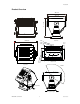
Introduction Product Overview 446 17.6in 445.7 17.5in 410 16.1in Front View 10.0in 16.9in 13.5in 12.8in 3.15in 528 20.8in 289.2 11.38in Side View 428 344 100 254 100 80 289.2 150 326 11.4in 5.9in 396 3.9in 15.
SETUP Lamp You will need to install a lamp prior to the initial operation of the fixture. Warning! When replacing the lamp, please wait 15 minutes after powering down to allow the unit to cool down! Always disconnect from main power prior to lamp replacement. Do not touch the envelope (glass area) of the bulb with bare hands. If this happens, clean the lamp with alcohol and wipe it with a lint free cloth before installation.
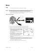
Setup L AM P AL IG NM ENT H O W - T O Often, after a new installation of a lamp, you will find that there is an uneven field of light or what is referred to as a hot spot. This is due to the most intense point of the lamp source not being positioned optimally within the reflector. There are three lamp alignment screws provided at the base of the projector head, behind the back cover plate.
Setup Installation O RI E NT AT IO N This fixture is designed to achieve an Ingress Protection Rating of 54 only when the fixture’s base is attached to a level horizontal surface. The ART-575W can be mounted both upright and on a truss system. W ar n in g It is important never to obstruct the fan or vents pathway. When selecting installation location, take into consideration lamp replacement access and routine maintenance. Safety cables should always be used.
Setup Power configuration The factory power settings will be printed on the fixtures serial label. Make sure that your local AC voltage matches that required by the fixture. 115V / 50Hz AC 230V / 60Hz AC The ART-575W is equipped with a 3-conductor electrical cable for connecting to an AC power supply. The cable enters the fixture through a cable gland that fits 5 to 10mm diameter cables.
OPERATING INSTRUCTIONS Operating Modes Stand-Alone mode will allow the independent execution of programs and a Master/Slave mode will allow the command of up to as many units you want in a synchronized manner. DMX control mode will provide the greatest flexibility and creativity. You can create an unlimited range of chase patterns at any speeds M AST E R/ S L AV E & ST AN D - AL O N E Stand-alone is an independent fixture operating state which basically means without the use of any controlling device.
Operating Instructions AC C E S S ING I NT E RN AL P RO G R AM S IN M AS T ER M O DE The programs are available while the fixture is set to the Master mode which is dipswitch 11 to ON and 12 to OFF. The programs are assigned to the first 42 channels or numerical values which can be initialized using the dipswitches. Each dipswitch has an associated value. These values are not printed on the fixture so it is very important that you read this section thoroughly.
Operating Instructions BU ILT - IN PRO G R AM S C H ART ON The channels address dipswitch settings for On and Off are displayed using binary numbers (1 and 0). 1 represents ON and 0 represent OFF. Remember that dipswitch 11 is also turned ON for Master mode.
Operating Instructions DM X M O DE Operating in a DMX Control mode environment gives the user the greatest flexibility when it comes to customizing or creating an environment. Simply address all fixtures sequentially and use any universal DMX controller. ON 1 2 3 4 5 6 7 8 9 10 11 12 DMX Mode: Set Dipswitches 11 & 12 to Off 1) Create the serial data link by connecting all fixtures in a daisy chain.
Operating Instructions ON CHANNEL 24 PIN # 5= 16 PIN # 4= 8 TOTAL= 24 1 1 2 3 4 4 8 2 5 6 7 8 9 10 11 12 16 64 256 32 128 42 – (32) = 10, Turn ON Dip # 6 10 – (8) = 2, Turn ON Dip # 4 2 – (2) = 0, Turn ON Dip # 2 RESOLVING ADDRESS USING SIMPLE MATH. ADDRESS 42 Binary values DIP SWITCH (DMX VALUE) 1 2 3 4 5 6 7 8 9 10 1 2 4 8 16 32 64 128 256 The ART-575W utilizes 8 control channels to operate in DMX mode.
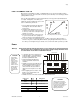
DMX Address Quick Reference Chart Dip Switch Position DMX DIP SWITCH SET #9 0 0 0 0 0 0 0 0 1 1 1 1 1 1 1 1 #8 0 0 0 0 1 1 1 1 0 0 0 0 1 1 1 1 1=ON #7 0 0 1 1 0 0 1 1 0 0 1 1 0 0 1 1 X=OFF or ON #6 0 1 0 1 0 1 0 1 0 1 0 1 0 1 0 1 32 64 96 128 160 192 224 256 288 320 352 384 416 448 480 0=OFF #1 #2 #3 #4 #5 0 0 0 0 0 1 0 0 0 0 1 33 65 97 129 161 193 225 257 289 321 353 385 417 449 481 0 1 0
Appendix APPENDIX DMX Primer There are 512 channels in a DMX-512 connection. Channels may be assigned in any manner. A fixture capable of receiving DMX-512 will require one or a number of sequential channels. The user must assign a starting address on the fixture that indicates the first channel reserved in the controller. There are many different types of DMX controllable fixtures and they all may vary in the total number of channels required. Choosing a start address should be planned in advance.
Appendix DMX Channel Values CHANNEL VALUE 1 000 255 Vector Control Speed for CMY and Dimmer 0 – 100% 2 000 255 Yellow 0 – 100% 3 000 255 Magenta 0 – 100% 4 000 255 Cyan 0 – 100% 5 000 255 Color Macros Red, Yellow (soft orange edge), Green, Cyan, Light Blue, Blue, Dark Blue, Purple, Magenta, White (soft pink edge) 6 000 255 Linear Dimmer 0 – 100% 7 000 255 Linear Zoom 7° – 40° 000 031 Programs Blackout Rapid Color Change: Red, Yellow, Green, Blue, Light Blue, Rose Red
Appendix Photo Metrics 40 Beampat h 6 7200 2900 1250 620 500 400 320 LUX 30 21.84 5 4 3 40 2 1 0 1 2 3 4 5 6 3 2.18 Dist ance(m) Diamet er(m) 5 3.64 10 7.28 15 10.92 20 14.56 25 18.20 23000 8200 2300 1200 800 620 560 LUX 15 1.83 20 2.45 25 3.06 30 3.67 2 1 0 1 2 ART-575W User Manual 7 7 Beampat h 3 0.37 5 0.61 10 1.
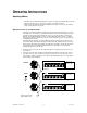
Appendix Dipswitch Location Remove fixture front cover, clips are located on both sides. Front of fixture exposed Dipswitch is accessible without removing PCB cover; however, a photograph has been taken with the PCB cover removed.
Appendix Maintenance To maintain optimum performance and minimize wear fixtures should be cleaned frequently. Usage and environment are contributing factors in determining frequency. As a general rule, fixtures should be cleaned at least twice a month. Dust build up reduces light output performance and can cause overheating. This can lead to reduced lamp life and increased mechanical wear. Be sure to power off fixture before conducting maintenance. Unplug fixture from power.
Appendix General Troubleshooting Applies to Symptom Solution(s) Lights Controllers Dimmers & Chaser Auto shut off Check fan thermal switch reset Beam is very dim or not bright Clean optical system or replace lamp Check 220/110v switch for proper setting Breaker/Fuse keeps blowing Check total load placed on device Chase is too slow Check users manual for speed adjustment Device has no power Check for power on Mains. Check device’s fuse.
Appendix Technical Specifications WEIGHT & DIMENSIONS Length........................................................................................................................ 521 mm (20.5 in) Width.......................................................................................................................... 470 mm (18,5 in) Height ........................................................................................................................... 533 mm (21 in) Weight................