DMX Mega Strobe™ II ST-800X USER MANUAL CHAUVET, 3000 N 29th Ct, Hollywood, FL 33020 U.S.A (800) 762-1084 – (954) 929-1115 FAX (954) 929-5560 www.chauvetlighting.
Table of Contents 1. BEFORE YOU BEGIN....................................................................................................................................................... 3 UNPACKING INSTRUCTIONS.............................................................................................................................................................................................. 3 CONTACT US ...............................................................................................
1. Before You Begin Unpacking Instructions Immediately upon receiving a product, carefully unpack the carton, check the contents to ensure that all parts are present, and have been received in good condition. Notify the shipper immediately and retain packing material for inspection if any parts appear damaged from shipping or the carton itself shows signs of mishandling. Save the carton and all packing materials.
Before You Begin Important Safety Information This product is designed for professional use. It is not intended for use in a household environment. This product presents risks of lethal or severe injury due to fire and heat, electric shock, ultraviolet radiation, lamp explosion, and injury from falls. Read this manual before installing or powering the fixture, follow the safety precautions listed below and observe all warnings in this manual and on the fixture.
2.
Introduction Product Overview Hanging Yoke Safety Glass DMX In AC Input DMX Out Side View ON OFF ST-800X User Manual Speed Rotary knob 256 Strobe Intensity 128 64 32 16 8 4 2 1 Term DMX Signal Termination ON – Active OFF – Non-active -Hz ON – 60Hz OFF – 50Hz DMX ADD 1 2 1 2 3 4 5 6 7 8 9 DIM SPEED Side View 6 2007-03-07/10:58
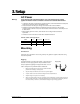
3. Setup AC Power Warning! Verify that the power requirement label on your unit matches the line voltage applied. All fixtures must be connected to circuits with a suitable Earth Ground. • To determine the power requirements for a particular fixture, see the label affixed to the back plate of the fixture or refer to the fixture’s specifications chart. • A fixture’s listed current rating is its average current draw under normal conditions.
Setup Fixture Linking You will need a serial data link to run light shows of one or more fixtures using a DMX-512 controller or to run synchronized shows on two or more fixtures set to a master/slave operating mode. The combined number of channels required by all the fixtures on a serial data link determines the number of fixtures the data link can support. The Thruster™ fixtures use 2 channels of DMX control. Important: Fixtures on a serial data link must be daisy chained in one single line.
Setup 3 - P i n t o 5 - P i n C o n ve r s i o n C h a r t Note! If you use a controller with a 5 pin DMX output connector, you will need to use a 5 pin to 3 pin adapter. CHAUVET Model No: DMX5M.
Lamp Installation When replacing the lamp, please wait 15 minutes after powering down to allow the unit to cool down! Always disconnect from main power prior to lamp replacement. Do not touch the envelope (glass area) of the bulb with bare hands. If this happens, clean the lamp with alcohol and wipe it with a lint free cloth before installation. Unscrew and release lamp wires from the main PCB. Unscrew grounding wire from PCB.
4. Operating Instructions Operating Modes • A stand-alone mode will allow the user to set the desired speed and intensity. • Master/Slave output provides for unison triggering of chained strobes. • DMX-512 control protocol allows remote control of the fixture via a universal DMX controller. Stand Alone The Stand Alone mode is activated automatically when the fixture is absent of a CH-751, SC-1000M or a DMX controller. Note! All dipswitches must be set to the OFF position.
Operating Instructions Setting the DMX Address Each fixture requires a "start address" from 1 to 511. A fixture requiring one or more channels for control begins to read the data on the channel indicated by the start address. For example, a fixture that occupies or uses 7 channels of DMX and was addressed to start on DMX channel 100, would read data from channels: 100, 101, 102, 103, 104, 105 and 106.
5. Appendix Returns Procedure Returned merchandise must be sent prepaid and in the original packing, call tags will not be issued. Package must be clearly labeled with a Return Merchandise Authorization Number (RA #). Products returned without an RA # will be refused. Call CHAUVET and request RA # prior to shipping the fixture. Be prepared to provide the model number, serial number and a brief description of the cause for the return.
Appendix Binary & DMX DIP-switch Addressing Each DIP-switch has an associated value. Adding the value of each switch in the ON position will provide the final address. Determining which switches to toggle ON given a specific desired address or value can be accomplished in the following manner. By subtracting the largest switch value possible from the selected start address which does not cause a negative number.
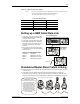
Appendix Binary Addressing Quick Reference Chart DMX & Binary Address Quick Reference Chart DIP-switch Position DMX DIP-SWITCH SET #9 0 0 0 0 0 0 0 0 1 1 1 1 1 1 1 1 0=OFF #8 0 0 0 0 1 1 1 1 0 0 0 0 1 1 1 1 1=ON #7 0 0 1 1 0 0 1 1 0 0 1 1 0 0 1 1 X=OFF or ON #6 0 1 0 1 0 1 0 1 0 1 0 1 0 1 0 1 32 64 96 128 160 192 224 256 288 320 352 384 416 448 480 #1 #2 #3 #4 #5 0 0 0 0 0 1 0 0 0 0 1 33 65 97 129 161
Appendix DMX Channel Values CHANNEL VALUE FUNCTION 1 000 Ù 255 Flash Rate Slow <> Fast 2 000 Ù 255 Flash Intensity Blackout <> Full Brightness Technical Specifications WEIGHT & DIMENSIONS Length........................................................................................................................... 320 mm (12.6 in) Width ............................................................................................................................ 207 mm (8.15 in) Height ............