User Manual
TABLE OF CONTENTS 1. Before You Begin................................................................................3 What Is Included ........................................................................................... 3 Unpacking Instructions .................................................................................. 3 Claims ................................................................................................................... 3 Text Conventions ...............................
1. BEFORE YOU BEGIN What Is Included Unpacking Instructions Claims Text Conventions Symbols • • Intimidator™ Spot LED 250 Hanging Bracket with Mounting Hardware • • • Power Cord Warranty Card Quick Reference Guide Carefully unpack the product immediately and check the container to make sure all the parts are in the package and are in good condition.
Product at a Glance Use on Dimmer Outdoor Use Sound-Activated DMX Master/Slave Safety Notes Auto Programs Auto-ranging Power Supply Replaceable Fuse User-Serviceable P P P x Please read the following Safety Notes carefully before working with the product. The Notes include important safety information about installation, usage, and maintenance. • • • • • • • • • • • • • • • • • • • • Page 4 of 20 x x P P P This product is not intended for permanent installation.
2. INTRODUCTION Product Overview Control Panel and Button Menu Power In Power Out Cooling Fan DMX Out DMX In Fuse Holder Intimidator™ Spot LED 250 User Manual Rev.
Product Dimensions Page 6 of 20 Intimidator™ Spot LED 250 User Manual Rev.
3. SETUP AC Power The Intimidator™ Spot LED 250 has an auto-ranging power supply and it can work with an input voltage range of 100~240 VAC, 50/60 Hz. To determine the product’s power requirements (circuit breaker, power outlet, and wiring), use the current value listed on the label affixed to the product’s back panel, or refer to the product’s specifications chart. The listed current rating indicates the product’s average current draw under normal conditions.
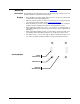
Mounting Before mounting the product, read and follow the Safety Notes. Orientation The Intimidator™ Spot LED 250 may be mounted in any position; however, make sure adequate ventilation is provided around the product. Rigging Mounting Diagram • Before deciding on a location, always make sure there is easy access to the product for maintenance and programming purposes. • Make sure that the structure or surface onto which you are mounting the product can support the product’s weight.
4. OPERATION Control Panel Operation To access the control panel functions, use the four buttons located underneath the display.
Configuration (DMX) Starting Address Set 1. 2. 3. the product in DMX mode to control with a DMX controller. Connect the product to a suitable power outlet. Turn the product on. Connect a DMX cable from the DMX output of the DMX controller to the DMX input socket on the product. When selecting a starting DMX address, always consider the number of DMX channels the selected DMX mode uses. If you choose a starting address that is too high, you could restrict the access to some of the product’s channels.
DMX Channel Assignments and Values 13-CH Channel Function Value Setting 1 Pan 000 ó 255 0–540° 2 Fine Pan 000 ó 255 Fine control of panning 3 4 5 Tilt Fine Tilt Speed 6 Color Wheel 000 ó 000 ó 000 ó 000 ó 007 ó 014 ó 021 ó 028 ó 035 ó 042 ó 049 ó 056 ó 065 ó 072 ó 079 ó 086 ó 093 ó 100 ó 107 ó 114 ó 121 ó 128 ó 255 255 255 006 013 020 027 034 041 048 055 064 071 078 085 092 099 106 113 120 127 191 7 Gobo Wheel 064 ó 072 ó 080 ó 088 ó 096 ó 104 ó 112 ó 120 ó 128 ó 192 ó 071 079 087 095 10
DMX Channel Assignments and Values (cont.) 13-CH (cont.
DMX Channel Assignments and Values (cont.) 8-CH Channel Function Value Setting 1 Pan 000 ó 255 0–540° 2 Tilt 000 ó 255 0–270° 3 Color Wheel 4 Gobo Wheel 5 Gobo Rotation 6 Prism 7 Dimmer 8 Shutter Intimidator™ Spot LED 250 User Manual Rev.
Configuration (Standalone) Set the product in one of the standalone modes to control without a DMX controller. 1. Connect the product to a suitable power outlet. 2. Turn the product on. Never connect a product that is operating in any standalone mode (either Static, Automatic, or Sound) to a DMX string connected to a DMX controller. Products in standalone mode may transmit DMX signals that could interfere with the DMX signals from the controller.
Display Orientation You are able to flip the LED display for easy readability in any mounting situation. To select your display angle: 1. Press repeatedly until diS shows on the display. 2. 3. Master/Slave Mode Reset Software Press or to select normal display mode (diS) or inverse display mode (r diS). Press .
Password Channel The Intimidator™ Spot LED 250 contains a password-protected mode which allows you to calibrate and troubleshoot any small issues you may have during normal operation. In order to access this mode, do the following: 1. Press and hold for at least 10 seconds. 2. Use the and buttons to enter the password: 2323. 3. Press . In this mode you have several options for adjustment.
Changing Gobos To change the gobos in the Intimidator™ Spot LED 250, you do not need to remove the gobo wheel. Simply: 1. Turn off and disconnect product from power. 2. Place the product on a flat, level surface with the front facing up. 3. Open the gobo-access plate by pushing it in the direction of the arrow. 4. Rotate the gobo wheel until the gobo that needs replacing is accessible. 5. Separate the gobo holder assembly away from the gobo wheel by pushing it forward and up.
5. TECHNICAL INFORMATION Product Maintenance Dust build-up reduces light output performance and can cause overheating. This can lead to reduction of the light source’s life. To maintain optimum performance and minimize wear, you should clean your lighting products at least twice a month. However, be aware that usage and environmental conditions may lead to more frequent cleaning. To clean the product, follow the instructions below: • Unplug the product from power.
In case you need to return a product or request support, follow the procedure below: • • • Contact Us If you live in the U.S., contact CHAUVET® World Headquarters. If you live in the UK or Ireland, contact CHAUVET® Europe Ltd. If you live in any other country, DO NOT contact CHAUVET®. Instead, contact your dealer. See the respective website for dealers’ contact details.
6. TECHNICAL SPECIFICATIONS Dimensions and Weight Length Width Height Weight 9.3 in (236 mm) 8.1 in (205 mm) 11.3 in (287 mm) 12.6 lbs (5.7 kg) Note: Dimensions in inches rounded to the nearest decimal digit. Power Light Source Photo Optic Thermal DMX Ordering Page 20 of 20 Power Supply Type Range Voltage Selection Switching (internal) 100~240 V, 50/60 Hz Auto-ranging Parameter 120 V, 60 Hz 230 V, 50 Hz Consumption 150 W 157 W Operating 1.3 A 0.