DMX-55 DMX Controller USER MANUAL Chauvet, 3000 N 29th Ct, Hollywood, FL 33020 U.S.A (800) 762-1084 – (954) 929-1115 FAX (954) 929-5560 www.chauvetlighting.
TABLE OF CONTENT BEFORE YOU BEGIN ...................................................................................................................................................... 3 WHAT IS INCLUDED................................................................................................................................................................................ 3 UNPACKING INSTRUCTIONS ..........................................................................................................
BEFORE YOU BEGIN What is included DMX-55 Controller DC 9~12V 500mA power adapter Manual with warranty card Unpacking Instructions Immediately upon receiving a fixture, carefully unpack the carton, check the contents to ensure that all parts are present, and have been received in good condition. Notify the shipper immediately and retain packing material for inspection if any parts appear damaged from shipping or the carton itself shows signs of mishandling. Save the carton and all packing materials.
INTRODUCTION Features Universal DMX-512 Controller 240 scene memory 192 DMX channels of control Polarity selector Fog control button Strobe 3 space 19" rack or table top mount Removable rubber edge guard Midi compatible Controls up to 12 intelligent lights 30 banks of 8 scenes Beat-activation, tap sync, auto run 6 sets of chases containing 240 scenes Assignable and reversible joystick Override button Reversible sliders Grab any fixture on the fly General Overview The DMX-
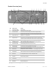
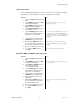
Introduction Product Overview (front) 1 2 21 17 3 10 9 11 12 14 15 13 5 6 18 23 7 16 8 Item 1 2 3 4 19 Button or Fader Function Scanner indicator LEDS Indicates the fixtures currently selected Scanner select buttons Scene select buttons 4 Channel faders 5 Page A Indicator LED 6 8 Program button Used to enter programming mode 12 13 LCD display window Mode Indicator LEDS Bank Up button Bank Down button 14 Tap Display button 15 Blackout button 16 17 18 19 20 21 22 23 24
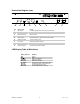
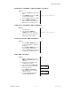
Connection Diagram (rear) 34 Item 27 28 29 30 31 32 33 34 35 27 28 29 35 30 Button or Fader Function DMX polarity switch May be used to correct signal polarity MIDI input port DMX output connector DC Input jack Strobe connector ON/OFF power switch Fog connector Audio input jack DMX input connector 31 32 33 For external triggering of Banks and Chases using a MIDI device DMX control signal Main power feed Chauvet Mono Strobe ¼” connector for built in strobe controller Turns the controller
Introduction Common Terms The following are common terms used in intelligent light programming. Blackout is a state by where all lighting fixtures light output are set to 0 or off, usually on a temporary basis. DMX-512 is an industry standard digital communication protocol used in entertainment lighting equipment. For more information read Sections “DMX Primer” and “DMX Control Mode” in the Appendix.
OPERATING INSTRUCTIONS Setup S ET T ING U P T H E SY ST EM 1) Place the DMX-55 on a leveled surface. Note! The DMX-55 can also be rack mounted, occupying 3U spaces by removing the outer rubber edge guard. 2) Plug the AC to DC power supply to the system back panel and to the mains outlet. 3) Plug in your DMX cable(s) to your intelligent lighting as described in the fixtures respective manual. For a quick Primer on DMX see the “DMX Primer” section in the Appendix of this manual.
Operating Instructions JO Y ST ICK S ET UP Because not all intelligent lighting fixtures are alike or share the same control attributes, the DMX-55 allows the user to assign the joystick the correct pan and tilt channel for every fixture. Notes Action 1) Press the Program button until the LED blinks. 2) Hold the MODE button and press FINE. The Reverse LED will light. 3) Hold the MODE button again and press FINE. The Assign LED will light.
Operating Instructions DE L ET ING A S C AN N E R’ S DM X CH AN N E L S ET T ING S Notes Action 1) Press the Program button until the LED blinks. 2) Hold the MODE button and press FINE. The Reverse LED will light. 3) Tap the Scanner button delete settings. 4) Press the MODE and AUTO/Del buttons at the same time. All LEDs will flash three times to confirm operation. Assign mode will also work in this case. CL E AR AL L SC AN N E R’ S DM X CH AN N E L S Notes Action 1) Turn the power off.
Operating Instructions SC E N E P RO G R AM M ING ENT ER ING PRO G R AM M ING M O DE 1) Press the Program button until the LED blinks. CR E AT E A S C E N E A scene is a static lighting state. The DMX-55 can save 240 scenes. Notes Action 1) Press the Program button until the LED blinks. 2) Position SPEED and FADE TIME sliders all the way down. 3) Select the SCANNERS you wish to include in your scene. You can select more than one fixture. 4) Compose a look by moving the sliders and joystick.
Operating Instructions CO PY SC AN N E R S ET T ING S This operation allows the user to copy the programming state of one scanner to another. This is especially useful when both scanners are of the same type. Notes Action 1) Hold and maintain the Scanner button to copy. 2) Tap another Scanner button to copy settings into. CO PY SC E N E Notes Action 1) Press the Program button until the LED blinks. 2) Use BANK and BANK buttons to change banks.
Operating Instructions 3) Tap the MIDI/Rec button. 4) Use BANK and BANK buttons to select the bank to copy to. 5) Tap the Music/Bankcopy button to execute the copy. 6) To exit programming mode press the Program button until the LED turns off. All LEDs wil flash three times to confirm process. Chase Programming A chase is created by using previously created scenes. Scenes become steps in a chase and can be arranged in any order you choose.
Operating Instructions AD D A ST E P Notes Action 1) Press the Program button until the LED blinks. 2) Press the corresponding button to the chase you wish to add a step to. 3) Press the TAP/Display button so that the LCD display shows the current step. 4) Use the BANK and BANK buttons to scroll to the step you wish to add a step after. 5) Press the MIDI/REC button. The LCD will display one step number higher than previous. 6) Tap the TAP/Display button again.
Operating Instructions DE L ET E AL L C H AS E S Notes Action 1) With the power off, press and hold the AUTO/Del and BANK buttons. 2) Turn controller back on and all chases will be cleared. Playback (Scenes) M ANU AL R UN SC EN E When power is first turned ON, the controller will be in manual scene mode. Notes Action 1) Make sure neither Music nor Auto LEDs are on. 2) Select the program BANK that stores the scene you want to run manually by using the BANK UP/DOWN.
Operating Instructions Playback (Chases) M ANU AL R UN C H AS E S This function allows the user to manually step through each individual step in a chase. Notes Action 1) When the power is first turned on the controller enters manual mode automatically. 2) Start a chase by pressing any one of the Chase buttons. 3) Press the Chase button again to deselect. AUT O R UN C H AS E S Notes Action 1) Press the AUTO/Del button to activate Auto mode. The Auto LED should light.
Operating Instructions Midi Operation The controller will only respond to MIDI commands on the MIDI channel which it is set to full stop. All MIDI control is performed using Note on commands. All other MIDI instructions are ignored. To stop a chase, send the blackout on note. Notes Action 1) Press and hold the MIDI/REC button for about 3 seconds. 2) Select the MIDI control channel (1~16) via the BANK UP/DOWN buttons to set. 3) Press and hold the MIDI/REC button for 3 seconds to save settings.
APPENDIX DMX Primer There are 512 channels in a DMX-512 connection. Channels may be assigned in any manner. A fixture capable of receiving DMX 512 will require one or a number of sequential channels. The user must assign a starting address on the fixture that indicates the first channel reserved in the controller. There are many different types of DMX controllable fixtures and they all may vary in the total number of channels required. Choosing a start address should be planned in advance.
Appendix Maintenance To maintain optimum performance and minimize wear fixtures should be cleaned frequently. Usage and environment are contributing factors in determining frequency. As a general rule, fixtures should be cleaned at least twice a month. Dust build up reduces light output performance and can cause overheating. This can lead to reduced lamp life and increased mechanical wear. Be sure to power off fixture before conducting maintenance. Unplug fixture from power.
Appendix General Troubleshooting Applies to Symptom Solution(s) Auto shut off Check fan thermal switch reset Beam is very dim or not bright Clean optical system or replace lamp Breaker/Fuse keeps blowing Check total load placed on device Chase is too slow Check users manual for speed adjustment Device has no power Check for power on Mains. Lights Foggers & Snow Controllers Dimmers & Chaser Check 220/110v switch for proper setting Check device’s fuse.
Appendix Technical Specifications WEIGHT & DIMENSIONS Length...................................................................................................................... 514 mm (20.25 in) Width..............................................................................................................................89 mm (3.5 in) Height ........................................................................................................................ 171 mm (6.75 in) Weight.................