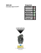
Snapshot DMX-690 Intimidator Spot 2.0 HTI™ Ok on Dimmer Outdoor OK Sound Activated DMX512 Master/Slave 115V/230V Switch Replaceable Fuse User Serviceable Duty Cycle USER MANUAL Chauvet, 3000 N 29th Ct, Hollywood, FL 33020 U.S.A. (800) 762-1084 – (954) 929-1115 FAX (954) 929-5560 www.chauvetlighting.
TABLE OF CONTENTS 1. BEFORE YOU BEGIN....................................................................................................................................................... 3 WHAT IS INCLUDED .............................................................................................................................................................. 3 UNPACKING INSTRUCTIONS ........................................................................................................................
1. BEFORE YOU BEGIN What is included ¾ ¾ ¾ ¾ ¾ 1 x Intimidator Spot 2.0 HTI™ 150W HTI Lamp Power Cord Warranty Card User Manual Unpacking Instructions Immediately upon receiving a fixture, carefully unpack the carton, check the contents to ensure that all parts are present, and have been received in good condition. Notify the shipper immediately and retain packing material for inspection if any parts appear damaged from shipping or the carton itself shows signs of mishandling.
Safety Instructions Please read these instructions carefully, which includes important information about the installation, usage and maintenance of this product. • • • • • • • • • • • • • Caution! Please keep this User Guide for future consultation. If you sell the unit to another user, be sure that they also receive this instruction booklet.
2. INTRODUCTION Features • • • • • • 6 to 8-channel DMX-512 moving yoke Pan: 540° / tilt: 270° Variable strobe/shutter Color wheel: 7 colors + white Rainbow color spin effect Rotating gobo wheel: 7 interchangeable, rotating gobos + open 5 metal, 2 dichroic gobos Gobo wheel spin effect Variable motorized dimmer (0 – 100%) Additional Features • • • • • • • • • • • • • Gobo size: 23.5mm outside, 17.5mm image, 0.
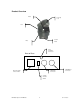
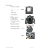
Product Overview Head Focusing Lens Yoke Control Panel Base Easy Controller Connector Rear of Base AC Power Input & Fuse Holder DMX Input Connector DMX Output Connector Voltage Selector Switch Intimidator Spot 2.
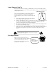
3. SETUP Lamp You will need to install a lamp prior to the initial operation of the fixture. A 150W HTI lamp is included. Warning! When replacing the lamp, please wait 15 minutes after powering down to allow the unit to cool down! Always disconnect from main power prior to lamp replacement. Do not touch the envelope (glass area) of the bulb with bare hands. If this happens, clean the lamp with alcohol and wipe it with a lint free cloth before installation.
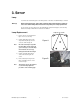
Lamp Alignment How-To Often, after a new installation of a lamp, you will find that there is an uneven field of light or what is refered to as a hot spot. This is due to the most intense point of the lamp source not being positioned optimally within the reflector. Lamp alignment screws There are three lamp alignment screws provided at the base of the fixture. Turning these screws allow you to optimize the projection quality of the spot as well as the overall intensity of the beam.
Replacing Gobos 1) Remove the four screws indicated in figure A to remove the back of the head. 2) Remove the four screws indicated in Figure A figure B to remove the front of the head. 3) Orient the fixture so that it looks like the fixture in figure C. 4) Remove the glue from the gobo (figure D) using tweezers. 5) Remove the retaining spring from the gobos. 6) Remove the existing gobo, and replace with a new gobo. 7) Replace the retaining spring.
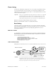
Fixture Linking You will need a serial data link to run light shows of one or more fixtures using a DMX-512 controller or to run synchronized shows on two or more fixtures set to a master/slave operating mode. The combined number of channels required by all the fixtures on a serial data link determines the number of fixtures the data link can support. Fixtures on a serial data link must be daisy chained in one single line.
3-PIN TO 5- PIN CON VER SION CHAR T Note! If you use a controller with a 5 pin DMX output connector, you will need to use a 5 pin to 3 pin adapter. CHAUVET Model No: DMX5M, or DMX5F.
Mounting ORIENTATION This fixture may be mounted in any position provided there is adequate room for ventilation. R IG G IN G Hanging Clamp It is important never to obstruct the fan or vents pathway. Mount the fixture using, a suitable “C” or “O” type clamp. Adjust the angle of the fixture by loosening both knobs and tilting the fixture. After finding the desired position, retighten both knobs.
4. OPERATING INSTRUCTIONS Navigating the Control Panel Access control panel functions using the four panel buttons located directly underneath the LCD Display. NOTE: The display will turn off after 30 seconds if no buttons are pushed. Button Function UP Used to access the menu or to scroll through top-level menu items.
Menu Map Intimidator Spot 2.
Menu Functions MENU OPTION DESCRIPTION DMX: The fixture will be controlled by a DMX signal coming from a DMX controller. The starting address must be selected, and can be set using the up and down buttons. Automatic – Master Unit: Sets the fixture to Master status for Master-Slave operation and the built in programs will be triggered automatically. No data link is required; all fixtures can be set to this mode for Stand-alone operation.
TO CHANGE TH E PAN RANGE: 1) Press until , 2) Use the and buttons to scroll through the three options. is 360°; Note: , or is displayed.. is 540°; is 180° These settings only apply if the fixture is in master/slave or stand-alone modes. These settings will not affect a fixture operating in DMX mode. TO CHANGE TH E TILT RA NGE : 1) Press until , 2) Use the and buttons to scroll through the three options. is 180°; Note: , or is displayed..
Operation Stand-Alone Mode (Sound-Active, Auto Mode, Easy Controller): This mode allows a single unit to run to the beat of the music, or the unit will auto change in Auto Mode. 1) Press until 2) Use the and buttons to scroll through until the desired mode is displayed and , press the button. , , or is auto mode; is displayed. is sound-active, is easy controller mode.
DMX Mode This mode allows the unit to be controlled by any universal DMX controller. If you are unfamiliar with DMX, please read the DMX Primer on page 21. is displayed. 1) Press until 2) Use the and buttons to select the desired address and press the button.
DMX Channel Values (8-bit mode) CHANNEL VALUE FUNCTION 1 000 Ù 255 Pan 0 – 540 (128 = halfway point) 2 000 Ù 255 Tilt 0 – 270 (128 = halfway point) 3 000 Ù 108 109 Ù 133 134 Ù 249 250 Ù 255 Shutter and Dimmer Closed Closed > Open Open Strobe (Fast > Slow) Open 4 000 Ù 015 016 Ù 031 032 Ù 047 048 Ù 063 064 Ù 079 080 Ù 095 096 Ù 111 112 Ù 127 128 Ù 191 192 Ù 255 Color Wheel White (Open) UV Pink Green Red Blue Yellow Magenta Scroll counter-clockwise (Slow > Fast) Scroll clockwise (Slow > Fast) 5
General Troubleshooting Applies to Symptom Solution(s) Lights Foggers & Snow Controllers Dimmers & Chaser Auto shut off Check fan thermal switch reset 9 Beam is very dim or not bright Clean optical system or replace lamp Check 220/110v switch for proper setting 9 Breaker/Fuse keeps blowing Check total load placed on device Chase is too slow Check users manual for speed adjustment 9 9 9 Device has no power Check for power on Mains. Check device’s fuse.
Technical Support Address: Service Dept. 3000 N 29th Ct, Hollywood, FL 33020 (U.S.A.) Support (Email): tech@chauvetlighting.com Telephone: (954) 929-1115 - (Press 4) Fax: (954) 929-5560 - (Attention: Service) Website: http://www.chauvetlighting.com 5. APPENDIX DMX Primer There are 512 channels in a DMX-512 connection. Channels may be assigned in any manner. A fixture capable of receiving DMX 512 will require one or a number of sequential channels.
Returns Procedure Returned merchandise must be sent prepaid and in the original packing, call tags will not be issued. Package must be clearly labeled with a Return Merchandise Authorization Number (RA #). Products returned without an RA # will be refused. Call CHAUVET and request RA # prior to shipping the fixture. Be prepared to provide the model number, serial number and a brief description of the cause for the return.
Technical Specifications WEIGHT & DIMENSIONS Length.............................................................................................................................. 16 in (406 mm) Width ............................................................................................................................... 10 in (254 mm) Height .................................................................................................................................9 in (229 mm) Weight .............