User Manual
TABLE OF CONTENTS 1. Before You Begin .......................................................................................................... 4 What Is Included ............................................................................................................................... 4 Unpacking Instructions ..................................................................................................................... 4 Claims ....................................................................
14CH .............................................................................................................................................. 22 DMX Assignments (Cont.) ...............................................................................................23 14CH .............................................................................................................................................. 23 DMX Assignments (Cont.) ..............................................................
1. BEFORE YOU BEGIN What Is Included • • Intimidator™ Wave IRC Hanging bracket with mounting hardware • • • Power cord Warranty card Quick Reference Guide Unpacking Instructions Carefully unpack the product immediately and check the container to make sure all the parts are in the package and are in good condition.
Product at a Glance Use on Dimmer Outdoor Use Sound-Activated DMX Master/Slave Safety Notes x x P P P Auto Programs Auto-ranging Power Supply Replaceable Fuse User-Serviceable P P P x These notes include important information about the mounting, usage, and maintenance of this product; read before using the product. • • • • • • • • • • • • • • • • • • • • Always connect the product to a grounded circuit to avoid the risk of electrocution.
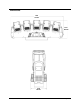
2. INTRODUCTION Overview Front Panel View Head 2 Head 1 Display Head 3 Head 4 Head 5 Control Buttons Back Panel View Fuse Holder Page 6 of 32 Power In Power Out DMX In DMX Out Intimidator™ Wave IRC User Manual Rev.
Dimensions 28 in 712 mm 9.6 in 243 mm 4.4 in 113 mm Intimidator™ Wave IRC User Manual Rev.
3. SETUP AC Power The Intimidator™ Wave IRC has an auto-ranging power supply and it can work with an input voltage range of 100–240 VAC, 50/60 Hz. To determine the product’s power requirements (circuit breaker, power outlet, and wiring), use the current value listed on the label affixed to the product’s back panel, or refer to the product’s specifications chart. The listed current rating indicates the product’s average current draw under normal conditions.
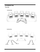
Power Linking The product provides power linking via the Edison/IEC outlet located in the front/back of the unit. st 1 Product Power Linking Diagram nd 2 Product rd 3 Product Additional Products You can power link up to 5 Intimidator™ Wave IRC units on 120 VAC or up to 13 Intimidator™ Wave IRC units on 230 VAC.
Mounting Before mounting the product, read and follow the safety recommendations indicated in the Safety Notes. For our CHAUVET® line of mounting clamps, go to www.chauvetlighting.com/cables-clamps-main.html/. Orientation The Intimidator™ Wave IRC may be mounted in any position; however, make sure adequate ventilation is provided around the product. Rigging • Before deciding on a location, always make sure there is easy access to the product for maintenance and programming.
4. OPERATION Control Panel Operation To access the control panel functions, use the four buttons located underneath the display.
DMX Personalities The Intimidator™ Wave IRC has two DMX personalities, a 34-channel personality and a 14-channel personality. To choose which DMX personality to use, follow the steps below: 1. Press
Master Auto The Master Auto 2-Head program allows a single Intimidator™ Wave IRC to control the actions of another Intimidator™ Wave IRC. The master unit will be set to operate in the M-2 program, 2-Head while the slave unit will be set to operate in either Slave S-1 or Slave S-2 mode. Program Configure the units as indicated below. Master unit: 1. Press
DMX ASSIGNMENTS 34CH Channel Function Value 1 Head 1 Tilt 000ó255 0–270° 2 Head 2 Tilt 000ó255 0–270° 3 Head 3 Tilt 000ó255 0–270° 4 Head 4 Tilt 000ó255 0–270° 5 Head 5 Tilt 000ó255 0–270° Percent/Setting 000ó047 No function 048ó055 Program 1 056ó063 Program 2 064ó071 Program 3 072ó079 Program 4 080ó087 Program 5 088ó095 Program 6 096ó103 Program 7 104ó111 Program 8 112ó119 Program 9 120ó127 Program 10 128ó135 Program 11 136ó143 Program 12 6 Head Tilt Programs 144ó151 Program 13 152ó159
DMX ASSIGNMENTS (CONT.
DMX ASSIGNMENTS (CONT.
DMX ASSIGNMENTS (CONT.
DMX ASSIGNMENTS (CONT.
DMX ASSIGNMENTS (CONT.) 34CH Channel Function Value Percent/Setting 196ó200 Program 37 201ó205 Program 38 206ó210 Program 39 211ó215 Program 40 216ó220 Program 41 30 Auto Programs (Cont.
DMX ASSIGNMENTS (CONT.) 34CH Channel Function Value Percent/Setting 000ó009 No function 010ó014 Move-in-black 015ó019 Cancel move-in-black 34 Settings (Set these values before setting other DMX channels.
DMX ASSIGNMENTS (CONT.
DMX ASSIGNMENTS (CONT.
DMX ASSIGNMENTS (CONT.
DMX ASSIGNMENTS (CONT.
DMX ASSIGNMENTS (CONT.) 14CH Channel Function Value Percent/Setting 176ó180 Program 33 181ó185 Program 34 186ó190 Program 35 191ó195 Program 36 196ó200 Program 37 201ó205 Program 38 206ó210 Program 39 10 Auto Programs (Cont.
DMX ASSIGNMENTS (CONT.) 14CH Channel Function Value Percent/Setting 000ó009 No function 010ó014 Move-in-black 015ó019 Cancel move-in-black 14 Settings (Set these values before setting other DMX channels.
Configuration (Standalone) Set the product in one of the standalone modes to control it without a DMX controller. Connect the product to a suitable power outlet. Never connect a product that is operating in any standalone mode (Static, Automatic, or Sound-Active) to a DMX string connected to a DMX controller. Products in standalone mode may transmit DMX signals that could interfere with the DMX signals from the controller. Sound-Active Mode To enable the Sound-Active mode, do the following: 1.
Display Blackout and Reverse You can flip the LED display for easy readability in any mounting situation or blackout the display entirely. To select your display angle: 1. Press
5. TECHNICAL INFORMATION Product Maintenance Dust build-up reduces light output performance and can cause overheating. This can lead to reduction of the light source’s life and mechanical wear. To maintain optimum performance and minimize wear, clean the product at least twice a month. However, usage and environmental conditions contribute to increased cleaning frequency. To clean the product, follow the instructions below: 1. Unplug the product from power. 2. Wait until the product is at room temperature.
6. TECHNICAL SPECIFICATIONS Dimensions and Weight Length Width Height Weight 28 in (712 mm) 4.4 in (113 mm) 9.6 in (243 mm) 17.2 lb (7.8 kg) Note: Dimensions in inches rounded to the nearest decimal digit. Power Light Source Photo Optic Thermal DMX Ordering Page 30 of 32 Power Supply Type Range Voltage Selection Switching (internal) 100 to 240 VAC, 50/60 Hz Auto-ranging Parameter 120 V, 60 Hz 230 V, 50 Hz Consumption 173 W 174 W Operating current 2.5 A 1.
RETURNS To return a product or request support: • In the U.S., contact Chauvet World Headquarters (see Contact Us). • In the UK or Ireland, contact Chauvet Europe Ltd. (see Contact Us). • In Mexico, contact Chauvet Mexico (see Contact Us). In any other country, DO NOT contact Chauvet. Contact your distributor. See www.chauvetlighting.com for distributors outside the U.S., United Kingdom, Ireland, or Mexico. If you live outside the U.S.
CONTACT US WORLD HEADQUARTERS - Chauvet General Information Technical Support Address:5200 NW 108th Avenue Voice: (954) 577-4455 (Press 4) Sunrise, FL 33351 Fax: (954) 756-8015 Voice: (954) 577-4455 Email: tech@chauvetlighting.com Fax: (954) 929-5560 World Wide Web www.chauvetlighting.com Toll free: (800) 762-1084 UNITED KINGDOM AND IRELAND - Chauvet Europe Ltd.