User Manual
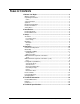
TABLE OF CONTENTS 1. Before You Begin................................................................................3 What Is Included ........................................................................................... 3 Unpacking Instructions .................................................................................. 3 Claims ................................................................................................................... 3 Text Conventions ...............................
1. BEFORE YOU BEGIN What Is Included Unpacking Instructions Claims Text Conventions Symbols • • Intimidator™ Spot LED 350 Hanging Bracket with Mounting Hardware • • • Power Cord Warranty Card Quick Reference Guide Carefully unpack the product immediately and check the container to make sure all the parts are in the package and are in good condition.
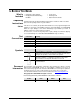
Product at a Glance Use on Dimmer Outdoor Use Sound-Activated DMX Master/Slave Safety Notes Auto Programs Auto-ranging Power Supply Replaceable Fuse User-Serviceable P P P x These notes include important information about the mounting, usage, and maintenance of this product; read before using the product. • • • • • • • • • • • • • • • • • • • • Page 4 of 20 x x P P P This product is not intended for permanent installation.
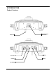
2. INTRODUCTION Product Overview Safety Loop Power Out Power In Control Panel and Button Menu DMX Out DMX In Fuse Holder Intimidator™ Spot LED 350 User Manual Rev.
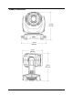
Product Dimensions Page 6 of 20 Intimidator™ Spot LED 350 User Manual Rev.
3. SETUP AC Power The Intimidator™ Spot LED 350 has an auto-ranging power supply and it can work with an input voltage range of 100~240 VAC, 50/60 Hz. To determine the product’s power requirements (circuit breaker, power outlet, and wiring), use the current value listed on the label affixed to the product’s back panel, or refer to the product’s specifications chart. The listed current rating indicates the product’s average current draw under normal conditions.
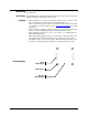
Power Linking The product provides power linking via the IEC outlet located in the back of the unit. 1st Product Power Linking Diagram 2nd Product 3rd Product Other products You can power link up to 3 Intimidator™ Spot LED 350 units on 120 VAC or up to 7 Intimidator™ Spot LED 350 units on 230 VAC.
Mounting Before mounting the product, read and follow the safety recommendations indicated in the Safety Notes. Orientation The Intimidator™ Spot LED 350 may be mounted in any position; however, make sure adequate ventilation is provided around the product. Rigging • Before deciding on a location for the product, always make sure there is easy access to the product for maintenance and programming purposes.
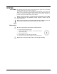
4. OPERATION Control Panel Operation To access the control panel functions, use the four buttons located underneath the display.
Configuration (DMX) Set the product in DMX mode to control with a DMX controller. 1. Connect the product to a suitable power outlet. 2. Turn the product on. 3. Starting Address Connect a DMX cable from the DMX output of the DMX controller to the DMX input socket on the product. When selecting a starting DMX address, always consider the number of DMX channels the selected DMX mode uses. If you choose a starting address that is too high, you could restrict the access to some of the product’s channels.
DMX Channel Assignments and Values 14-CH Page 12 of 20 Channel Function Value Setting 1 Pan 000 ó 255 0–540° 2 Fine Pan 000 ó 255 Fine control of panning 3 4 5 Tilt Fine Tilt Speed 6 Color Wheel 000 ó 000 ó 000 ó 000 ó 007 ó 014 ó 021 ó 028 ó 035 ó 042 ó 049 ó 056 ó 064 ó 071 ó 078 ó 085 ó 092 ó 099 ó 106 ó 113 ó 120 ó 128 ó 255 255 255 006 013 020 027 034 041 048 055 063 070 077 084 091 098 105 112 119 127 191 7 Gobo Wheel 064 ó 072 ó 080 ó 088 ó 096 ó 104 ó 112 ó 120 ó 128 ó 192 ó 071
DMX Channel Assignments and Values (cont.) 14-CH (cont.) Channel Function 8 Gobo Rotation 9 Prism 10 11 Focus Dimmer 12 Shutter 13 Control Functions 14 Movement Macros Intimidator™ Spot LED 350 User Manual Rev.
8-CH Page 14 of 20 Channel Function Value Setting 1 Pan 000 ó 255 0–540° 2 Tilt 000 ó 255 0–270° 3 Color Wheel 000 ó 007 ó 014 ó 021 ó 028 ó 035 ó 042 ó 049 ó 056 ó 064 ó 071 ó 078 ó 085 ó 092 ó 099 ó 106 ó 113 ó 120 ó 128 ó 192 ó 006 013 020 027 034 041 048 055 063 070 077 084 091 098 105 112 119 127 191 255 White Yellow Pink Green Red Light Blue Kelly Green Orange Dark Blue White + Yellow Yellow + Pink Pink + Green Green + Red Red + Light Blue Light Blue + Kelly Green Kelly Green + Orange
Configuration (Standalone) Set the product in one of the standalone modes to control without a DMX controller. 1. Connect the product to power. 2. Turn the product on. Never connect a product that is operating in any standalone mode (either Automatic or Sound-Active) to a DMX string connected to a DMX controller. Products in standalone mode may transmit DMX signals that could interfere with the DMX signals from the controller. Sound-Active Mode To enable the Sound-Active mode, do the following. 1.
Master/Slave Mode Reset Software The Master/Slave mode allows a single Intimidator™ Spot LED 350 unit (the “master”) to control the actions of one or more Intimidator™ Spot LED 350 units (the “slaves”) without the need of a DMX controller. The master unit will be set to operate in either Automatic or Sound-Active mode, while the slave units will be set to operate in Slave mode. Once set and connected, the slave units will operate in unison with the master unit. Configure the units as indicated below.
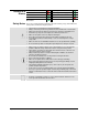
Changing Gobos To change the gobos in the Intimidator™ Spot LED 350, do not remove the gobo wheel. Simply: 1. Turn off and disconnect product from power outlet. 2. Place the product on a flat, level surface with the front facing up. 3. Access the gobo plate by removing the cover on the moving head. By hand, gently pry up the right side, then push right with the indented handles. NOTE: If you expose the driver board, you are on the wrong side of the head.
5. TECHNICAL INFORMATION Product Maintenance Dust build up reduces light output performance and can cause overheating. This can lead to reduction of the light source’s life. To maintain optimum performance and minimize wear, you should clean your lighting products at least twice a month. However, be aware that usage and environmental conditions could be contributing factors to increase the cleaning frequency. To clean the product, follow the instructions below: • Unplug the product from power.
To return a product or request support: • • • In the U.S., contact CHAUVET® World Headquarters (see below). In the UK or Ireland, contact CHAUVET® Europe Ltd. (see below). In any other country, DO NOT contact CHAUVET®. Contact your distributor. See www.chauvetlighting.com for distributors outside the U.S., United Kingdom, or Ireland. Outside the U.S., United Kingdom, or Ireland, contact your distributor and follow their instructions on how to return CHAUVET® products to them.
6. TECHNICAL SPECIFICATIONS Dimensions and Weight Length Width Height Weight 10.6 in (268 mm) 13.4 in (340 mm) 15.4 in (392 mm) 22.7 lbs (10.3 kg) Note: Dimensions in inches rounded to the nearest decimal digit. Power Light Source Photo Optic Thermal DMX Ordering Page 20 of 20 Power Supply Type Range Voltage Selection Switching (internal) 100~240 V, 50/60 Hz Auto-ranging Parameter 120 V, 60 Hz 230 V, 50 Hz Consumption 272 W 285 W Operating 2.2 A 1.