User Manual
TABLE OF CONTENTS 1. Before You Begin ............................................................................. 3 What Is Included ........................................................................................... 3 Unpacking Instructions .................................................................................. 3 Text Conventions .......................................................................................... 3 Icons ...........................................................
1. BEFORE YOU BEGIN What Is Included • • • • • 1 x Intimidator™ Scan LED 200 1 x Mounting Bracket kit 1 x Power Cord 1 x Warranty Card 1 x User Manual Unpacking Instructions Immediately upon receiving this product, carefully unpack it and check the container in which you received it. Make sure that you have received all the parts indicated above and that they are all in good condition.
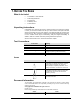
Product at a Glance Use on Dimmer Outdoor Use Sound Activated DMX Master/Slave Auto Programs Auto-ranging Power Supply Replaceable Fuse User Serviceable Duty Cycle Safety Notes Please read the following notes carefully because they include important safety information about the installation, usage, and maintenance of this product. Page 4 of 20 • Keep this User Manual for future consultation. If you sell this product to another user, be sure that they also receive this document.
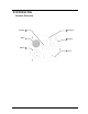
2. INTRODUCTION Product Overview Fuseholder DMX In Microphone Power Out DMX Out Power In Intimidator™ Scan LED 200 User Manual (Rev.
Product Dimensions Page 6 of 20 Intimidator™ Scan LED 200 User Manual (Rev.
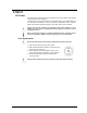
3. SETUP AC Power This product has an auto-ranging power supply and it can work with an input voltage range of 100~240 VAC, 50/60 Hz. To determine the power requirements for a particular fixture, see the label affixed to the back plate of the fixture or refer to the fixture’s specifications chart. A fixture’s listed current rating indicates its average current draw under normal conditions.
Power Linking This fixture provides power linking via the Edison outlet located in the bottom of the unit. Please see the diagram below for further explanation. To other fixtures Fixture #3 Power Linking Diagram Fixture #2 Fixture #1 You can power link up to 8 Intimidator™ Scan LED 200 units on 120 VAC.
Mounting Orientation The Intimidator™ Scan LED 200 may be mounted in any position, provided there is adequate room for ventilation around it. Rigging Before deciding on a location for this product, always make sure that it will be easy to access the unit for maintenance and programming purposes. Make sure that the structure or surface onto which you are mounting this product can support its weight. Please see the Technical Specifications section of this manual for weight information.
4. OPERATION Control Panel Operation To access the control panel functions, use the four buttons located underneath the display.
DMX Operation Set this product in DMX mode to control it with a DMX controller. 1) Connect this product to a suitable power outlet. 2) Turn this product on. 3) Connect a DMX cable from the DMX output of the DMX controller to the DMX input socket of this product. Starting Address When selecting a starting DMX address, always consider the number of DMX channels the selected DMX mode uses. If you choose a starting address that is too high, you could restrict the access to some of the fixture’s channels.
Standalone Operation Master/Slave Mode (Sound-Active, Auto Mode) This mode allows a single unit, the master, to operate in one of the standalone modes, while one or more fixtures, slaves, synchronize their responses to the master. Master: The master fixture may be set in any of the STANDALONE modes: sound-active, fast, or slow. Slave: 1) Press until one of the standalone modes appears on the LED screen (SLAu, nStS, nAFA, nASL). 2) Using and , select SLAu. 3) Press .
Service Mode Hidden Menu Map This fixture has a hidden menu. The purpose of this menu is to adjust the home position (electronic adjustment) of the attributes listed below.
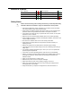
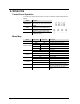
DMX Channel Assignments and Values 8-Channel Mode \ Channel Function 1 2 Pan Tilt 3 Color 4 Shutter 5 Dimmer 6 Gobo Wheel Value Setting 000 255 000 255 000 007 008 015 016 023 024 031 032 039 040 047 048 055 056 063 064 071 072 079 080 087 088 095 096 103 104 111 112 119 120 127 128 191 192 255 000 003 004 007 008 215 216 255 000 255 0°~180° 0°~90° Open (white) Dark Blue Yellow Pink Green Red Blue Salmon Pink White/dark blue Dark blue/yellow
Continued from previous page 8-Channel Mode (Cont.
5-Channel Mode \ Channel Page 16 of 20 Function 1 2 Pan Tilt 3 Color 4 Shutter 5 Gobo Wheel Value Setting 000 255 000 255 000 007 008 015 016 023 024 031 032 039 040 047 048 055 056 063 064 071 072 079 080 087 088 095 096 103 104 111 112 119 120 127 128 191 192 255 000 003 004 007 008 215 216 255 000 007 008 015 016 023 024 031 032 039 040 047 048 055 056 063 064 071 072 079 080 087 088 095 096 103 104 111 112 119 12
5. TECHNICAL INFORMATION General Maintenance Dust build up reduces light output performance and can cause overheating. This can lead to reduction of the light source’s life or mechanical wear. To maintain optimum performance and minimize wear, you should clean your lighting fixtures at least twice a month. However, be aware that usage and environmental conditions could be contributing factors to increase the cleaning frequency.
General Troubleshooting Symptom Circuit breaker or fuse keeps blowing Product does not power up Fixture does not respond to DMX Intermittent DMX Problems Possible Cause Possible Action Excessive load on the circuit Make sure that the total load does not exceed 80% of the breaker or fuse nominal current Short circuit along the power lines Check the power lines and power cords No energy on power outlet Check power outlet Change to another outlet Loose or damaged power cord Check the power cord B
Returns Procedure The user must send the merchandise prepaid, in the original box, and with its original packing and accessories. CHAUVET® will not issue call tags. Call CHAUVET® and request a Return Merchandise Authorization (RMA) number before shipping the fixture. Be prepared to provide the model number, serial number, and a brief description of the cause for the return. The user must clearly label the package with a Return Merchandise Authorization (RMA) number.
6. TECHNICAL SPECIFICATIONS Dimensions and Weight Length Width Height Weight 13.2 in (335 mm) 6.6 in (168 mm) 14.5 in (368 mm) 7.5 lbs (3.4 kg) Note: Dimensions in inches rounded to the nearest decimal digit. Power Power Supply Type Range Voltage Selection Switching (internal) 100~240 V, 50/60 Hz Auto-ranging Parameter 120 V, 60 Hz 230 V, 50 Hz Consumption 68 W 67 W Operating 1A 0.