User Manual
TABLE OF CONTENTS 1. BEFORE YOU BEGIN ....................................................................................................................................................... 3 WHAT IS INCLUDED ................................................................................................................................................................................ 3 UNPACKING INSTRUCTIONS ....................................................................................................
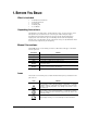
1. BEFORE YOU BEGIN What is included • • • • • 1 x Intimidator™ Scan LED 300 1 x Mounting bracket kit 1 x Power Cord 1 x Warranty Card 1 x User Manual Unpacking Instructions Immediately upon receiving a fixture, carefully unpack the carton, check the contents to ensure that all parts are present, and have been received in good condition. Notify the shipper immediately and retain packing material for inspection if any parts appear damaged from shipping or the carton itself shows signs of mishandling.
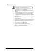
Safety Instructions Please read these instructions carefully. It includes important information about the installation, usage and maintenance of this product. • • • • • • • • • • • • • • 1. Before You Begin Please keep this User Manual for future consultation. If you sell the unit to another user, be sure that they also receive this instruction booklet.
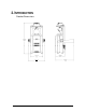
2. INTRODUCTION Product Dimensions 2.
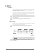
Product Overview Safety Bracket Adjustment Knob Voltage Selection Switch (115/230 VAC) DMX In Power In DMX Out Power Out Fuseholder 2.
3. SETUP AC Power This fixture is switchable and runs on either 115 VAC, 60 Hz or 230 VAC, 50 Hz power. Before powering on the unit, make sure the line voltage to which you are connecting it matches the current setting on the voltage selection switch. To determine the power requirements for a particular fixture, see the label affixed to the back plate of the fixture or refer to the fixture’s specifications chart. A fixture’s listed current rating indicates its average current draw under normal conditions.
Mounting Orientation The Intimidator™ Scan LED 300 may be mounted in any position provided there is adequate room for ventilation. Rigging Be sure that the structure can support the weight of the fixture. Please see the “Technical Specifications” section of this manual for a detailed weight listing. Mount the fixture securely. This may be done with a screw, nut and bolt, or a hanging clamp. The hole in each bracket is 13 mm in size. When rigging, consider routine maintenance and control panel access.
4. OPERATING INSTRUCTIONS Using the Control Panel Access control panel functions using the four buttons located directly underneath the LED display on the included wired remote.
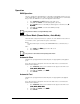
Operation DMX Operation This is the operating mode which will allow for control with an external DMX controller. You must set the starting address for this mode. If this is your first time using DMX, then it is recommended that you refer to the “DMX Primer” section in the “Appendix” of this manual. 1. 2. 3. 4. 5. Press until d*** appears on the LED screen. Using and , select the starting address (001~512).
Sound-Active This fixture has a preprogrammed, sound triggered chase. Access this via the control panel on the front of the fixture. Adjust the microphone sensitivity from the control panel. Please see the chart below for further explanation. 1. Press until one of the standalone modes appears on the LED screen (SLAv, 2. 3. NStS, NAFA, NASL). Using and , select NStS. Press . The microphone will only respond to low frequencies (bass).
DMX Channel Values 11-CH Mode CHANNEL VALUE FUNCTION 1 000 Ù 255 Pan 0°~180° 2 000 Ù 255 Tilt 0°~90° 3 000 Ù 006 007 Ù 013 014 Ù 020 021 Ù 027 028 Ù 034 035 Ù 041 042 Ù 048 049 Ù 055 056 Ù 063 064 Ù 070 071 Ù 077 078 Ù 084 085 Ù 091 092 Ù 098 099 Ù 105 106 Ù 112 113 Ù 119 120 Ù 127 128 Ù 191 192 Ù 255 Color Open (white) Yellow Pink Green Peachblow Blue Kelly Red Dark blue White/yellow (split colors) Yellow/pink (split colors) Pink/green (split colors) Green/peach blow (split colors) Peachblow/blu
7-CH Mode CHANNEL VALUE FUNCTION 000 Ù 255 Pan 0°~180° 2 000 Ù 255 Tilt 0°~90° 3 000 Ù 006 007 Ù 013 014 Ù 020 021 Ù 027 028 Ù 034 035 Ù 041 042 Ù 048 049 Ù 055 056 Ù 063 064 Ù 070 071 Ù 077 078 Ù 084 085 Ù 091 092 Ù 098 099 Ù 105 106 Ù 112 113 Ù 119 120 Ù 127 128 Ù 191 192 Ù 255 Color Open (white) Yellow Pink Green Peachblow Blue Kelly Red Dark blue White/yellow (split colors) Yellow/pink (split colors) Pink/green (split colors) Green/peach blow (split colors) Peachblow/blue (split colors) Blue/K
5. APPENDIX General Troubleshooting SYMPTOM Breaker/Fuse keeps blowing Device does not power up POSSIBLE CAUSE(S) • Excessive circuit load • Check total load placed on the electrical circuit. • Short circuit along the power wires • Check for a short in the electrical wiring (internal and/or external). • No power • Loose power cord • Check for power on Mains.
DMX Primer There are 512 channels in a DMX connection. A fixture capable of receiving DMX will require one or a number of sequential channels. The user must assign a starting address on the fixture that indicates the first channel reserved in the controller. There are many different types of DMX controllable fixtures and they all may vary in the total number of channels required. Choosing a start address should be planned in advance. Channels should never overlap.
Cable Connectors Cabling must have a male XLR connector on one end and a female XLR connector on the other end. DMX connector configuration COMMON INPUT 1 3 1 3 2 DMX + 2 DMX - OUTPUT Terminator To avoid signal transmission problems and interference, it is always advisable to connect a DMX signal terminator. 1 3 2 120 ohm ¼ W resistor between pin 2 (DMX -) and pin 3 (DMX +) on the output of the last fixture Do not allow contact between the common and the fixture’s chassis ground.
3-Pin to 5-Pin Conversion Chart If you use a controller with a 5-pin DMX output connector, you will need to use a 5-pin to 3-pin adapter. The chart below details a proper cable conversion: 3-PIN TO 5-PIN CONVERSION CHART Conductor 3-Pin Female (Output) 5-Pin Male (Input) Ground/Shield Pin 1 Pin 1 Data ( - ) signal Pin 2 Pin 2 Data ( + ) signal Pin 3 Pin 3 Not used Pin 4 Not used Pin 5 Setting up a DMX Daisy Chain 1.
General Maintenance To maintain optimum performance and minimize wear, fixtures should be cleaned frequently. Usage and environment are contributing factors in determining frequency. As a general rule, fixtures should be cleaned at least twice a month. Dust build up reduces light output performance and can cause overheating. This can lead to reduced lamp life and increased mechanical wear. Be sure to power off fixture before conducting maintenance. • Unplug fixture from power.
TECHNICAL SPECIFICATIONS WEIGHT & DIMENSIONS Length .............................................................................................................. 11 in (279 mm) Width ................................................................................................................ 10 in (254 mm) Height............................................................................................................ 18.9 in (478 mm) Weight .............................................................
CONTACT US World Wide General Information CHAUVET® th 5200 NW 108 Ave Sunrise, FL 33351 voice: 954.929.1115 fax: 954.929.5560 toll free: 800.762.1084 Technical Support CHAUVET® th 5200 NW 108 Ave Sunrise, FL 33351 voice: 954.929.1115 (Press 4) fax: 954.929.5560 (Attention: Service) World Wide Web www.chauvetlighting.