User Manual LASER LIGHT AVOID DIRECT EYE EXPOSURE CLASS IIIa LASER PRODUCT CLASSIFIED PER 21 CFR 1040.10 & .11 Complies with US FDA CDRH laser safety standards 21 CFR 1040.10 & 1040.11.
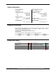
Contact Information World Headquarters CHAUVET® General Information Address: Voice: Fax: Toll free: United Kingdom & Ireland CHAUVET® Europe Ltd. General Information 5200 NW 108th Avenue Sunrise, FL 33351 (954) 929-1115 (954) 929-5560 (800) 762-1084 Technical Support Voice: Fax: Email: (954) 929-1115 (Press 4) (954) 756-8015 tech@chauvetlighting.
TABLE OF CONTENTS 1. Before You Begin ................................................................................................................ 4 What Is Included ................................................................................................................. 4 Unpacking Instructions ........................................................................................................ 4 Claims .........................................................................................
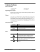
1. BEFORE YOU BEGIN What Is Included 1 x Scorpion™ GBC 1 x Power Cord 1 x Warranty Card 1 x User Manual Unpacking Instructions Immediately upon receiving this product, carefully unpack it and check the container in which you received it. Make sure that you have received all the parts indicated above and that they are all in good condition.
Safety Notes CAUTION! The use of optical instruments with this product will increase eye hazard. Please read the following notes carefully because they include important safety information about the installation, usage, and maintenance of this product. Keep this User Manual for future consultation. If you sell this product to another user, be sure that they also receive this document.
Non Interlocked Housing Warning This unit contains high power laser devices internally. Do not open the laser housing, due to potential exposure to unsafe levels of laser radiation. The laser power levels, accessible if the unit is opened, can cause instant blindness, skin burns, and fires. Laser Safety Notes STOP AND READ ALL THE LASER SAFETY NOTES BELOW Laser Light is different from any other light sources with which you may be familiar.
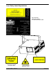
Laser Safety Labels Reproduction EXPLANATORY, MANUFACTURER’S ID & CERTIFICATION LABEL CAUTION – CLASS 3B LASER RADIATION WHEN OPEN.
Laser Emission Data LASER EXPOSURE Laser light - Avoid direct eye contact! Further guidelines and safety programs for safe use of lasers can be found in the ANSI Z136.1 Standard “For Safe Use of Lasers”, available from the Laser Institute of America: www.laserinstitute.org. Many local governments, corporations, agencies, military and others, require all lasers to be used under the guidelines of ANSI Z136.1. Laser Display guidance can be obtained via the International Laser Display Association: www.
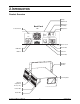
2.
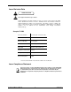
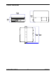
Product Dimensions Scorpion™ GBC User Manual 10 August 2011
3. SETUP AC Power This product runs on 100~240 VAC, 50/60 Hz. Before powering on the unit, make sure the line voltage to which you are connecting it is within the range of accepted voltages. Always connect the product to a switched circuit. Never connect the product to a rheostat (variable resistor) or dimmer circuit, even if the rheostat or dimmer channel is used only as a 0 to 100% switch.
Fuse Replacement 1. 2. 3. With a flat head screwdriver wedge the fuse holder out of its housing. Remove the damaged fuse from its holder and replace with exact same type fuse. Insert the fuse holder back in its place and reconnect power. The fuse is located inside this Disconnect the power cord before replacing a fuse and always replace with the same type fuse. Mounting Orientation This product may be mounted in any safe position, provided there is adequate room for ventilation.
Proper Usage This product is for overhead mounting only. For safety purposes, CHAUVET® recommends mounting your lighting effect products on steady elevated platforms or sturdy overhead supports using suitable hanging clamps. In all cases, you must use safety cables. You can obtain appropriate mounting hardware from your lighting vendor. International laser safety regulations require that laser products must be operated in the fashion illustrated below, with a minimum of 3 meters (9.
4. OPERATION Control Panel Access control panel functions using the four panel buttons located directly underneath the LED Display.
DMX Channel Summary CHANNEL FUNCTION 1 Control Mode 2 Pattern Selection 3 Color selection 4 Color Changing Speed 5 Zoom 6 X Axis Move (Pan) 7 Y Axis Move (Tilt) 8 Y Axis Roll 9 X Axis Roll 10 Z Axis Rotate Standalone Operation Automatic This product has preprogrammed automatic programs. These are accessed via the LED display on the back panel of the product. Please see the instructions below for further explanation. 1. 2. 3.
Master/Slave Operation When operating more than one product in standalone mode, it is possible to link them in a master/slave configuration. This is when one or more slave products will operate identically to the master product. Please see the instructions below for further explanation on how to set a product to slave mode. 1. 2. Press until slave mode appears on the LED display. See the chart under menu functions to identify this. Press .
DMX Channel Values CHANNEL VALUE FUNCTION 000 017 018 035 036 053 054 071 072 089 090 107 108 125 126 143 144 161 162 179 180 197 198 215 216 233 234 255 Control Mode Manual Mode (use channels 2~10 in this mode) Automatic fast (blue) Automatic slow (blue) Automatic fast (green) Automatic slow (green) Automatic fast (cyan) Automatic slow (cyan) Automatic Fast (mixed) Automatic Slow (mixed) Sound (blue) Sound (green) Sound (cyan) Sound (mixed) Random (Auto) 2 000 255 Patter
Channel 2 Values (Pattern Selection) Value Pattern Value Pattern Value Pattern Value 000~007 064~071 128~135 190~197 008~015 072~079 136~143 198~205 016~023 080~087 144~151 206~213 024~031 088~095 152~159 214~221 032~039 096~103 160~167 222~229 040~047 104~111 168~175 230~237 048~055 112~119 176~181 238~245 056~063 120~127 182~189 246~255 Scorpion™ GBC User Manual 18 Pattern August 2011
5. TECHNICAL INFORMATION General Troubleshooting Symptom Applies to Solution(s) Lights Foggers & Snow Controllers Dimmers& Chaser Breaker/Fuse keeps blowing Check total load placed on device Chase is too slow Check user manual for speed adjustment Device has no power Check for power on Mains. Check device’s fuse. (internal and/or external) Loss of signal Use only DMX cables Install terminator Note: Keep DMX cables separated from power cables or black lights.
Returns Procedure Returned merchandise must be sent prepaid and in the original packing, call tags will not be issued. Package must be clearly labeled with a Return Merchandise Authorization Number (RMA #). Products returned without an RMA # will be refused. Call CHAUVET® and request RMA # prior to shipping the product. Be prepared to provide the model number, serial number and a brief description of the cause for the return.
DMX Primer There are 512 channels in a DMX connection. Channels may be assigned in any manner. A product capable of receiving DMX will require one or a number of sequential channels. The user must assign a starting address on the product that indicates the first channel reserved in the controller. There are many different types of DMX controllable products and they all may vary in the total number of channels required. Choosing a start address should be planned in advance. Channels should never overlap.
Data Cabling To link products together you must obtain data cables. You can purchase CHAUVET® certified DMX cables directly from a dealer/distributor or construct your own cable. If you choose to create your own cable, use data-grade cables that can carry a high quality signal and are less prone to electromagnetic interference. DMX Data Cable Use a Belden© 9841 or equivalent cable which meets the specifications for EIA RS-485 applications.
Product Linking You will need a serial data link to run light shows of one or more products using a DMX controller or to run synchronized shows on two or more products set to a master/slave operating mode. The combined number of channels required by all the products on a serial data link determines the number of products the data link can support. Products on a serial data link must be daisy chained in one single line.
TECHNICAL SPECIFICATIONS WEIGHT & DIMENSIONS Length ........................................................................................................11.3 in (287 mm) Width ..........................................................................................................13.4 in (340 mm) Height ...........................................................................................................9.1 in (230 mm) Weight .........................................................................