User Manual
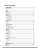
TABLE OF CONTENTS 1. Before You Begin ...................................................................................................................3 What Is Included.............................................................................................................................................3 Unpacking Instructions ..................................................................................................................................3 Claims ....................................
1. Before You Begin | What Is Included 1. BEFORE YOU BEGIN What Is Included • • • • Obey™ 6 External Power Supply Warranty Card Quick Reference Guide Unpacking Instructions Carefully unpack the Obey ™ 6 and check that all the parts are in the package, and are in good condition. Claims If the box, or any of the contents, appear damaged from shipping, save all the packaging and file a claim with the carrier immediately.
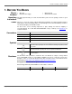
1. Before You Begin | Product at a Glance Product at a Glance Safety Notes Use on Dimmer x Auto Program x Outdoor Use x Auto-Ranging Power Supply P Sound-Activated P Replaceable Fuse x DMX P User-Serviceable x Master/Slave x These notes include important information about the mounting, use, and maintenance of this product. Read these notes before using the product. • • • • • Always connect the product to a grounded circuit. Make sure the power cord is not crimped or damaged.
2. Introduction | Features 2. INTRODUCTION Features • • • • • • • Controls up to 6 fixtures individually with up to 6 channels per fixture. Controls the lights in 6 different groups for a variety of looks. Includes 18 chases. Includes 24 built-in colors. Includes manual color mixing. Includes auto color changes and color fades with adjustable speeds and sound activation. Includes master dimmer control and strobing.
2. Introduction | Front Panel Overview Front Panel Overview The board is laid out with the fixture buttons on the top left, the color preset and chase buttons on the bottom left, the faders to the right—with color bump buttons above them, and the sound and strobe buttons to the far right. The diagram below shows the front panel and identifies each button and fader. See Back Panel View for information about the back panel and its ports.
2. Introduction | Front Panel View Control Descriptions Item Description – Buttons that select lights and the LEDs that indicate when lights are selected. These buttons are inclusive. Pressing one, then another, selects both lights. Pressing the button a second time deselects the light. Button that puts the selected lights into Color Fade mode and the LED that indicates when the selected lights are in Color Fade mode.
2. Introduction | Back Panel View Control Descriptions Item or Back Panel View Description Fader that controls: • the addition of UV in all modes Button that: • stops strobing in all modes other than Manual mode • activates, pauses, and deactivates the strobe function when in Manual mode The LED indicates when strobing is activated. This button is used in combination with . See Strobe Function for more information.
3. Setup | AC Power 3. SETUP AC Power The Obey™ 6 has an auto-ranging external power supply, that can work with an input voltage range of 100 to 240 VAC, 50/60 Hz. It runs on 9 VDC, 500 mA. Before turning on the power, make sure the line voltage is within the range of accepted voltages as listed on the label affixed to the product or as described in Technical Specifications. The listed rating indicates the average current draw under normal conditions.
3. Setup | Setting Up The Board Setting Up The Board The Obey™ 6 should be set up where the operator can see the lights they are programming. The board must be connected to the lights with DMX cables and the lights must be addressed correctly. The sections below describe DMX cabling and DMX addressing. DMX Cabling DMX cabling is required to send DMX signals from the board to the lights. To DMX cable the lights, do the following: 1.
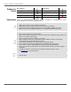
3. Setup | Faders DMX Addressing The following chart shows the Obey™ 6 DMX starting addresses and ranges, and the Chart corresponding fixture buttons. Starting Address Range Fixture Button 1 1–6 7 7-12 13 13-18 19 19-24 25 25-30 31 31-36 After the products are addressed, the board controls them with the buttons. For example: • • Faders Lights addressed at 1 are selected with .
4. Operation | Selecting Lights 4. OPERATION Selecting Lights Lights are selected by pressing one or more buttons. Pressing selects any and all lights in the DMX chain that are addressed at 1. Pressing and selects any and all lights in the DMX chain that are addressed at 1 or 7. See DMX Addressing of Lights and DMX Addressing Chart for more information.
4. Operation | Color Macro Mode Color Macro Mode Color Macro mode turns the fader into a fader that moves through a series of colors as it moves from bottom to top. See the diagram below. White Violet Blue UV Green Amber Red No Light • • Auto Mode To go into Color Macro mode, do the following: 1. Select lights by pressing buttons. The LEDs of the selected lights turn on. 2. Press . The Color Macro LED turns on. 3. Use to set the brightness. 4.
4. Operation | Chase Mode Chase Mode Chase mode uses the buttons to select specific color change sequences (chases). The speed, fade time, and intensity of each chase can be adjusted. See Chase Map for specific information about the colors in each chase. To go into Chases mode, do the following: 1. 2. 3. 4. 5. 6. Select lights by pressing buttons. The LEDs of the selected lights turn on. Press . The Chases LED turns on. Use to set the brightness.
4. Operation | Preset Mode Preset Mode Preset mode uses the buttons to select a specific color, as labeled on the board. To use Preset mode, do the following: 1. 2. 3. 4. 5. 6. Select lights by pressing buttons. The LEDs of the selected lights turn on. Press . The Preset LED turns on. Press a button. Use to set the brightness. Use to set the timing of the Master Dimmer function. Use to strobe the color.
4. Operation | Preset Mode Strobe Function Activating the strobe function in Manual mode suspends color mixing. Once the Strobe function is In Manual Mode activated, strobing can be adjusted with . Then, the Strobe function can be exited, while the strobing continues, so that all the faders can return to controlling colors. Strobing can also be stopped and restarted without changing colors.
4. Operation | Strobe Function Strobe Function Strobing is available in all modes by moving the fader, except Manual mode. In Manual mode the fader controls the amber color, and must be reassigned to control strobing. See Strobe Function In Manual Mode for instructions on strobing in Manual mode In all other modes the strobing is started, and the strobe speed is set, by moving the fader. The Strobe LED will flash to indicate that the strobe function is active.
4. Operation | Blackout Blackout Blackout stops all signals from the board to the lights. It is useful for quickly, and temporarily, stopping all lighting. Blackout does not affect the settings in the board. When blackout is cancelled the lights begin again. Blackout is activated at any time by pressing . The Blackout LED turns on when blackout is active. Blackout is cancelled by pressing again. The Blackout LED is off when blackout is not active.
4. Operation | Tips and Tricks Tricks If the Strobe LED does not go off when the board is in Manual mode, try the following: If the Strobe LED is flashing 1. Press twice or bring all the way down. The LED will stop flashing and remain on. 2. Press once. The Strobe LED will turn off. If the Strobe LED is on continuously 1. Press it once and the LED will turn off. If the lights seem unresponsive when going into Color Fade, Auto, or Chase mode, try the following: 1.
5. Technical Information 5. TECHNICAL INFORMATION Maintenance To maintain optimum performance and minimize wear, fixtures should be cleaned frequently. Usage and environment are contributing factors in determining frequency. As a general rule, fixtures should be cleaned at least twice a month. Dust build-up reduces light output performance and can cause overheating. This can lead to reduced lamp life and increased mechanical wear. Be sure to power off fixture before conducting maintenance. 1. 2. 3. 4.
Returns RETURNS To return a product or request support: • • • • In the U.S., contact CHAUVET® World Headquarters (see below). In the UK or Ireland, contact CHAUVET® Europe Ltd. (see below). In Mexico, contact CHAUVET® Mexico (see below). In any other country, DO NOT contact CHAUVET®. Contact your distributor. See www.chauvetlighting.com for distributors outside the U.S., United Kingdom, or Ireland. If you live outside the U.S.
Contact Us CONTACT US WORLD HEADQUARTERS - CHAUVET® General Information Address:5200 NW 108th Avenue Sunrise, FL 33351 Voice: (954) 577-4455 Fax: (954) 929-5560 Toll free: (800) 762-1084 Technical Support Voice: Fax: Email: (954) 577-4455 (Press 4) (954) 756-8015 tech@chauvetlighting.com World Wide Web www.chauvetlighting.com UNITED KINGDOM AND IRELAND - CHAUVET® Europe Ltd.