User Manual
TABLE OF CONTENTS 1. Before You Begin................................................................................3 What Is Included ........................................................................................... 3 Unpacking Instructions .................................................................................. 3 Claims ................................................................................................................... 3 Text Conventions ...............................
1. BEFORE YOU BEGIN What Is Included • • • • 1 x PiX™ PAR 12 1 x Power Cord 1 x Warranty Card 1 x Quick Reference Guide Unpacking Instructions Immediately upon receipt, carefully unpack the product and check the container to make sure you have received all the parts indicated above in good condition.
Product at a Glance Use on Dimmer Outdoor Use Sound Activated DMX Master/Slave Safety Notes Auto Programs Auto-ranging Power Supply Replaceable Fuse User Serviceable P P P x Please read the following Safety Notes carefully before working with the product. The Notes include important safety information about installation, usage, and maintenance. • • • • • • • • • • • • • • • • • • • Page 4 of 20 x x P P P Always connect the product to a grounded circuit to avoid the risk of electrocution.
2. INTRODUCTION Product Overview LED Display 5-pin DMX Connectors Fuse Holder Power Out 3-pin DMX Connectors PiX™ PAR 12 User Manual Rev.
Product Dimensions Page 6 of 20 PiX™ PAR 12 User Manual Rev.
3. SETUP AC Power The PiX™ PAR 12 has an auto-ranging power supply and it can work with an input voltage range of 100~240 VAC, 50/60 Hz. To determine the product’s power requirements (circuit breaker, power outlet, and wiring), use the current value listed on the label affixed to the product’s back panel, or refer to the product’s specifications chart. The listed current rating indicates the product’s average current draw under normal conditions.
Power Linking The product provides power linking via the IEC outlet located in the back of the unit. Please see the diagram below for further explanation. 1st Product Power Linking Diagram 2nd Product 3rd Product Other products You can power link up to ten (10) PiX™ PAR 12 units on 120 VAC or up to eighteen (18) PiX™ PAR 12 units on 230 VAC.
Mounting Before mounting the product, read and follow the safety recommendations indicated in the Safety Notes section (page 2 of this manual). Orientation The PiX™ PAR 12 may be mounted in any position; however, make sure adequate ventilation is provided around the product. Rigging • Before deciding on a location for the product, always make sure there is easy access to the product for maintenance and programming purposes.
4. OPERATION Control Panel Operation To access the control panel functions, use the four buttons located underneath the display. Please refer to the Product Overview to see the button locations on the control panel.
Configuration (DMX) DMX Personalities and Starting Address Set 1. 2. 3. the product in DMX mode to control with a DMX controller. Connect the product to a suitable power outlet. Turn the product on. Connect a DMX cable from the DMX output of the DMX controller to the DMX input socket on the product. The PiX™ PAR 12 has four DMX personalities, from a 3-channel mode for basic control to a 36-channel mode with more advanced control over the lights.
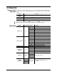
DMX Channel Assignments and Values 3-CH 9-CH Channel Function Value Setting 1 Red 000 ó 255 0-100% 2 Green 000 ó 255 0-100% 3 Blue 000 ó 255 0-100% Channel Function Value Setting 1 Dimmer 000 ó 255 0-100% 2 Red 000 ó 255 0-100% 3 4 Green Blue 5 Color Macros 6 Strobe 000 ó 000 ó 000 ó 011 ó 201 ó 206 ó 211 ó 216 ó 221 ó 226 ó 231 ó 236 ó 241 ó 246 ó 251 ó 000 ó 010 ó 255 255 010 200 205 210 215 220 225 230 235 240 245 250 255 009 255 0-100% 0-100% No function Color Macros Whi
Continued from previous page Channel 12-CH Function 7 Auto Programs 8 Auto Program Speed 9 Dimmer Curve Channel Function Value 000 ó 010 ó 020 ó 030 ó 040 ó 050 ó 060 ó 070 ó 080 ó 090 ó 100 ó 110 ó 120 ó 130 ó 140 ó 150 ó 160 ó 170 ó 180 ó 190 ó 200 ó 210 ó 220 ó 230 ó 240 ó 250 ó 000 ó 000 ó 052 ó 102 ó 153 ó 204 ó 009 019 029 039 049 059 069 079 089 099 109 119 129 139 149 159 169 179 189 199 209 219 229 239 249 255 255 051 101 152 203 255 Value Setting No function Fade transition (7 color
36-CH Page 14 of 20 Channel Function Value Setting 1 Red 000 ó 255 0-100% 2 Green 000 ó 255 0-100% 3 Blue 000 ó 255 0-100% 4 5 6 Red Green Blue 000 ó 255 0-100% 000 ó 255 0-100% 000 ó 255 0-100% … … … … … … … … … … … … 34 35 36 Red Green Blue 000 ó 255 0-100% 000 ó 255 0-100% 000 ó 255 0-100% LED 1 2 12 PiX™ PAR 12 User Manual Rev.
Configuration (Standalone) Set the product in one of the standalone modes to control without a DMX controller. 1. Connect the product to a suitable power outlet. 2. Turn the product on. Never connect a product that is operating in any standalone mode (Static, Automatic, or Sound) to a DMX string connected to a DMX controller. Products in standalone mode may transmit DMX signals that could interfere with the DMX signals from the controller.
Master/Slave Mode Page 16 of 20 The Master/Slave mode allows a single PiX™ PAR 12 unit (the “master”) to control the actions of one or more PiX™ PAR 12 units (the “slaves”) without the need of a DMX controller. The master unit will be set to operate in an automatic mode, while the slave units will be set to operate in slave mode. Once set and connected, the slave units will operate in unison with the master unit. Configure the units as indicated below. Slave units: 1.
5. TECHNICAL INFORMATION Product Maintenance Dust build-up reduces light output performance and can cause overheating. This can lead to reduction of the light source’s life. To maintain optimum performance and minimize wear, you should clean your lighting products at least twice a month. However, be aware that usage and environmental conditions could be contributing factors to increase the cleaning frequency. To clean the product, follow the instructions below: • Unplug the product from power.
General Troubleshooting Symptom Possible Cause Excessive load on the circuit Make sure that the total load does not exceed 80% of the breaker or fuse nominal current Short circuit along the power lines Check the power lines and power cords No energy on power outlet Check power outlet Change to another outlet Loose or damaged power cord Check the power cord Blown fuse Replace blown fuse with a good one of the same type and rating Internal problem Send product for repair Wrong starting address o
Contact Procedure CHAUVET® Contact Information In case you need to return a product or request support, follow the procedure below: • • • If you live in the U.S., contact CHAUVET® World Headquarters (see below). If you live in the UK or Ireland, contact CHAUVET® Europe Ltd. (see below). If you live in any other country, DO NOT contact CHAUVET®. Instead, contact your distributor of record. Refer to our website for contact details of distributors outside the U.S., United Kingdom, or Ireland.
6. TECHNICAL SPECIFICATIONS Dimensions and Weight Length Width Height Weight 10.7 in (271 mm) 10.2 in (260 mm) 3.5 in (88 mm) 6.9 lbs (3.1 kg) Note: Dimensions in inches rounded to the nearest decimal digit. Power Light Source Photo Optic Thermal DMX Ordering Page 20 of 20 Power Supply Type Range Voltage Selection Switching (internal) 100~240 V, 50/60 Hz Auto-ranging Parameter 120 V, 60 Hz 230 V, 50 Hz Consumption 92 W 96 W Operating 0.8 A 0.