User Manual
TABLE OF CONTENTS 1. BEFORE YOU BEGIN............................................................................................................................................................ 3 WHAT IS INCLUDED ...................................................................................................................................................................... 3 UNPACKING INSTRUCTIONS ..........................................................................................................
1. BEFORE YOU BEGIN What is Included · · · · 1 x Abyss™ LED 3.0 1 x Power Cord 1 x Warranty Card 1 x User Manual Unpacking Instructions Immediately upon receiving a fixture, carefully unpack the carton. Check the contents to ensure that all parts are included and received in good condition.
Safety Instructions Please read these instructions carefully. It includes important information about the installation, usage, and maintenance of this product. · · · · · · · · · · · · · · 1. Before You Begin Please keep this User Manual for future reference. If you sell the unit to another user, be sure that they also receive this instruction booklet.
2. INTRODUCTION Product Overview Mounting Bracket DMX In DIP Switches Safety Power Out Bracket Adjustment Knob Bracket Adjustment Knob Power In DMX Out 2.
3. SETUP AC Power This fixture runs on 100~240 VAC, 50/60 Hz. Before powering on the unit, make sure the line voltage to which you are connecting is within the range of accepted voltages. To determine the power requirements for a particular fixture, see the label affixed to the back plate of the fixture or refer to the fixture’s specifications chart. A fixture’s listed current rating indicates its average current draw under normal conditions. Always connect the fixture to a switched circuit.
Mounting Orientation The Abyss™ LED 3.0 may be mounted in any position, provided there is adequate room for ventilation. Rigging Be sure that the structure can support the weight of the fixture. Please see the “Technical Specifications” section of this manual for a detailed weight listing. Mount the fixture securely. This may be done with a screw, nut and bolt, or a hanging clamp. The hole in each bracket is 13 mm in size. When rigging consider routine maintenance and control panel access.
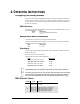
4. OPERATING INSTRUCTIONS Configuring the Starting Address The Abyss™ LED 3.0 fixture uses two DMX channels. The highest channel that the fixture may be set to in order to function properly is 511. Any address higher than this will prevent access to all of the channels. If this is your first time using DMX, we recommend reading the “DMX Primer” section in the “Appendix”. DMX Operation This is the operating mode which will allow for control with an external DMX controller.
5. APPENDIX General Troubleshooting SYMPTOM Breaker/Fuse keeps blowing Device does not power up POSSIBLE CAUSE(S) · Excessive circuit load · Check total load placed on the electrical circuit. · Short circuit along the power wires · Check for a short in the electrical wiring (internal and/or external). · No power · Loose power cord · Check for power on Mains.
DMX Primer There are 512 channels in a DMX connection. A fixture capable of receiving DMX will require one or a number of sequential channels. The user must assign a starting address on the fixture that indicates the first channel reserved in the controller. There are many different types of DMX controllable fixtures and they all may vary in the total number of channels required. Choosing a start address should be planned in advance. Channels should never overlap.
Cable Connectors Cabling must have a male XLR connector on one end and a female XLR connector on the other end. DMX connector configuration COMMON INPUT 1 3 1 3 2 DMX + 2 DMX - OUTPUT Terminator To avoid signal transmission problems and interference, it is always advisable to connect a DMX signal terminator. 1 3 2 120 ohm ¼ W resistor between pin 2 (DMX -) and pin 3 (DMX +) on the output of the last fixture Do not allow contact between the common and the fixture’s chassis ground.
3-Pin to 5-Pin Conversion Chart If you use a controller with a 5-pin DMX output connector, you will need to use a 5-pin to 3-pin adapter. The chart below details a proper cable conversion: 3-PIN TO 5-PIN CONVERSION CHART Conductor 3-Pin Female (Output) 5-Pin Male (Input) Ground/Shield Pin 1 Pin 1 Data ( - ) signal Pin 2 Pin 2 Data ( + ) signal Pin 3 Pin 3 Not used Pin 4 Not used Pin 5 Setting up a DMX Daisy Chain 1.
General Maintenance To maintain optimum performance and minimize wear, fixtures should be cleaned frequently. Usage and environment are contributing factors in determining frequency. As a general rule, fixtures should be cleaned at least twice a month. Dust build up reduces light output performance and can cause overheating. This can lead to reduced life and increased mechanical wear. Be sure to power off fixture before conducting maintenance. · Unplug fixture from power.
TECHNICAL SPECIFICATIONS WEIGHT & DIMENSIONS Length ................................................................................................................9.6 in (243 mm) Width ................................................................................................................10.2 in (260 mm) Height .................................................................................................................7.4 in (188 mm) Weight ......................................................
CONTACT US Wor l d Wi d e Technical Specifications General Information CHAUVET® th 5200 NW 108 Ave Sunrise, FL 33351 voice: 954.929.1115 fax: 954.929.5560 toll free: 800.762.1084 Technical Support CHAUVET® th 5200 NW 108 Ave Sunrise, FL 33351 voice: 954.929.1115 (Press 4) fax: 954.929.5560 (Attention: Service) World Wide Web www.chauvetlighting.