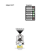
Snapshot Q-Spot 152™ OK on Dimmer Outdoor OK Sound Activated DMX512 Master/Slave Multitap Transformer Replaceable Fuse User Serviceable Duty Cycle USER MANUAL Chauvet, 3000 N 29th Ct, Hollywood, FL 33020 U.S.A. (800) 762-1084 – (954) 929-1115 FAX (954) 929-5560 www.chauvetlighting.
TABLE OF CONTENTS 1. BEFORE YOU BEGIN................................................................................................................................ 3 WHAT IS INCLUDED......................................................................................................................................... 3 UNPACKING INSTRUCTIONS ............................................................................................................................. 3 AC POWER ............................
1. BEFORE YOU BEGIN What is included ¾ ¾ ¾ ¾ ¾ ¾ 1 x Q-Spot 152™ 150W HTI Lamp 5 additional metal gobos Power Cord Warranty Card User Manual Unpacking Instructions Immediately upon receiving a fixture, carefully unpack the carton, check the contents to ensure that all parts are present, and have been received in good condition. Notify the shipper immediately and retain packing material for inspection if any parts appear damaged from shipping or the carton itself shows signs of mishandling.
Contact Us World Wide General Information Chauvet Lighting th 3000 North 29 Court Hollywood, FL 33020 voice: 954.929.1115 fax: 954.929.5560 toll free: 800.762.1084 Technical Support Chauvet Lighting th 3000 North 29 Court Hollywood, FL 33020 voice: 954.929.1115 (Press 4) fax: 954.929.5560 (Attention: Service) World Wide Web www.chauvetlighting.
2.
Product Overview Focus Adjust Head Arm Base Control Panel Voltage Select Switch (Internal) DMX Output IEC Power Connector DMX Input Power Switch Easy Controller Input (sold separately, release date TBA) Microphone Q-Spot 152 User Manual 6 2007-07-09/17:40
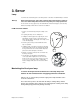
3. SETUP Lamp You will need to install a lamp prior to the initial operation of the fixture. A 150W HTI lamp is included. Warning! When replacing the lamp, please wait 15 minutes after powering down to allow the unit to cool down! Always disconnect from main power prior to lamp replacement. Do not touch the envelope (glass area) of the bulb with bare hands. If this happens, clean the lamp with alcohol and wipe it with a lint free cloth before installation. LA M P IN STA LLA T ION 1.
LA MP ALIGN M ENT HOW- TO Often, after a new installation of a lamp, you will find that there is an uneven field of light or what is referred A to as a hot spot. This is due to the most intense point B of the lamp source not being positioned optimally S2 within the reflector. C There are three lamp alignment screws provided at the base of the projector head. Turning these screws allow you to optimize the projection quality of the spot as well as the overall intensity of the beam.
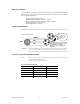
Replacing Gobos 1) Remove the four screws indicated in figure A to remove the bottom of the Figure A head. 2) Remove the glue from the gobo using tweezers. 3) Remove the retaining spring from the gobo (figure B). 4) Remove the existing gobo, and replace with a new gobo. 5) Replace the retaining spring. 6) If desired, add three small dabs of high-temperature silicone glue to the Figure B retaining spring. 7) Repeat steps 4-6 as many times as necessary to replace all desired gobos.
D MX DA TA CAB LE Use a Belden© 9841 or equivalent cable which meets the specifications for EIA RS-485 applications. Standard microphone cables cannot transmit DMX data reliably over long distances. The cable will have the following characteristics: 2-conductor twisted pair plus a shield Maximum capacitance between conductors – 30 pF/ft. Maximum capacitance between conductor and shield – 55 pF/ft. Maximum resistance of 20 ohms / 1000 ft.
Setting up a DMX Serial Data Link Universal DMX Controller 1. Connect the (male) 3 pin connector side of the DMX cable to the output (female) 3 pin connector of the controller. 2. Connect the end of the cable coming from the controller which will have a (female) 3 pin connector to the input connector of the next fixture consisting of a (male) 3 pin connector. 3. Then, proceed to connect from the output as stated above to the input of the following fixture and so on.
Mounting ORIENTATION This fixture may be mounted in any position provided there is adequate room for ventilation. R IG G IN G Hanging Clamp It is important never to obstruct the fan or vents pathway. Mount the fixture using, a suitable “C” or “O” type clamp. Adjust the angle of the fixture by loosening both knobs and tilting the fixture. After finding the desired position, retighten both knobs.
4. OPERATING INSTRUCTIONS Navigating the Control Panel Access control panel functions using the four panel buttons located directly underneath the LCD Display.
Menu Map Menu 1-Address 1-Address select: 001 2-Reset 2-Reset select: No 2-Reset select: Yes 3-Operation select: DMX 3-Operation 3-Operation select: Auto1 4-Display 4-Display select: 60 close 3-Operation select: Sound1 4-Display select: Bright 5-Pan 3-Operation select: Slave 5-Pan select: Normal 3-Operation select: Random 3-Operation select: Auto2 5-Pan select: Reverse 3-Operation select: Sound2 6-Tilt 6-Tilt select: Normal 6-Tilt select: Reverse 7-Color 7-Color select: Step 7-Color sele
Menu Functions MENU OPTION DESCRIPTION 1-Address Set the DMX address for the fixture. 2-Reset Reset the fixture. 3-Operation Select operating mode: DMX, Auto 1, Auto 2, Music 1, Music 2, Slave, or Random. Auto and Music modes set the fixture to Master/Stand-alone mode. 4-Display Change whether display backlight turns off after 60 seconds or not. 5-Pan Pan normal or inverted. 6-Tilt Tilt normal or inverted. 7-Color Set the color wheel to linear control (split colors), or snap to color.
TO CHANGE TH E CHANN ELS SETTING: 1) Press the
Master/Slave Mode (Master Sound, Master Auto): This mode will allow you to link up to 32 units together without a controller. 1) Use standard DMX cables to daisy chain your units together via the DMX connector on the rear of the units. For longer cable runs we suggest a terminator at the last fixture. For more information about terminators, see page 10. 2) Choose a unit to function as the Master. This unit must be the first unit in the line. 3) Press the
DMX Channel Values in Advanced Mode CHANNEL VALUE FUNCTION 1 000 Ù 255 Pan 2 000 Ù 255 Tilt 3 000 Ù 255 Fine pan 4 000 Ù 255 Fine tilt 5 000 Ù 255 Vector Speed: (Normal > Slow) 6 000 Ù 014 015 Ù 029 030 Ù 044 045 Ù 059 060 Ù 074 075 Ù 089 090 Ù 104 105 Ù 119 120 Ù 134 135 Ù 149 150 Ù 255 Color Wheel White (Open) Red Orange Yellow Green Blue Magenta Pink Cyan UV Color scroll: Slow > Fast 7 000 Ù 009 010 Ù 019 020 Ù 029 030 Ù 039 040 Ù 049 050 Ù 059 060 Ù 069 070 Ù 079 080 Ù 099 100 Ù 119
12 Q-Spot 152 User Manual 128 Ù 139 140 Ù 169 170 Ù 199 200 Ù 229 230 Ù 255 Reset No effect Sound Active 1 Sound Active 2 Random 000 Ù 009 010 Ù 019 020 Ù 029 030 Ù 039 040 Ù 049 050 Ù 059 060 Ù 069 070 Ù 079 080 Ù 089 090 Ù 099 100 Ù 109 110 Ù 119 120 Ù 129 130 Ù 139 140 Ù 149 150 Ù 159 160 Ù 169 170 Ù 179 180 Ù 189 190 Ù 199 200 Ù 209 210 Ù 219 220 Ù 229 230 Ù 239 240 Ù 249 250 Ù 255 Effect No Effect Effect 1 Effect 2 Effect 3 Effect 4 Effect 5 Effect 6 Effect 7 Effect 8 Effect 9 Effect 10 Effect 11
DMX Channel Values in Basic Mode CHANNEL VALUE FUNCTION 1 000 Ù 255 Pan 2 000 Ù 255 Tilt 3 000 Ù 014 015 Ù 029 030 Ù 044 045 Ù 059 060 Ù 074 075 Ù 089 090 Ù 104 105 Ù 119 120 Ù 134 135 Ù 149 150 Ù 255 Color Wheel White (Open) Red Orange Yellow Green Blue Magenta Pink Cyan UV Color scroll: Slow > Fast 4 000 Ù 009 010 Ù 019 020 Ù 029 030 Ù 039 040 Ù 049 050 Ù 059 060 Ù 069 070 Ù 079 080 Ù 099 100 Ù 119 120 Ù 139 140 Ù 159 160 Ù 179 180 Ù 199 200 Ù 219 220 Ù 255 Gobo Wheel Open Gobo 1 Gobo 2 Gobo
General Troubleshooting Applies to Symptom Solution(s) Lights Foggers & Snow Controllers Dimmers & Chaser Auto shut off Check fan thermal switch reset 9 Beam is very dim or not bright Clean optical system or replace lamp Check 220/110v switch for proper setting 9 Breaker/Fuse keeps blowing Check total load placed on device Chase is too slow Check users manual for speed adjustment 9 9 9 Device has no power Check for power on Mains. Check device’s fuse.
Address: Service Dept. 3000 N 29th Ct, Hollywood, FL 33020 (U.S.A.) Support (Email): tech@chauvetlighting.com Telephone: (954) 929-1115 - (Press 4) Fax: (954) 929-5560 - (Attention: Service) Website: http://www.chauvetlighting.com 5. APPENDIX DMX Primer There are 512 channels in a DMX-512 connection. Channels may be assigned in any manner. A fixture capable of receiving DMX 512 will require one or a number of sequential channels.
General Maintenance To maintain optimum performance and minimize wear fixtures should be cleaned frequently. Usage and environment are contributing factors in determining frequency. As a general rule, fixtures should be cleaned at least twice a month. Dust build up reduces light output performance and can cause overheating. This can lead to reduced lamp life and increased mechanical wear. Be sure to power off fixture before conducting maintenance. Unplug fixture from power.
Technical Specifications WEIGHT & DIMENSIONS Length........................................................................................................................... 13.8 in (350 mm) Width ............................................................................................................................ 11.3 in (287 mm) Height ........................................................................................................................... 18.5 in (470 mm) Weight .................