
User manual


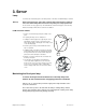


Replacing Gobos
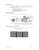
Figure A
Figure B
1) Remove the four screws indicated in
figure A to remove the bottom of the
head.
2) Remove the glue from the gobo u
tweezers.
sing
3) Remove the retaining spring from the
gobo (figure B).
4) Remove the existing gobo, and
replace with a new gobo.
5) Replace the retaining spring.
6) If desired, add three small dabs of
high-temperature silicone glue to the
retaining spring.
7) Repeat steps 4-6 as many times as
necessary to replace all desired
gobos.
8) Replace the bottom cover and
retighten the four screws removed in
step 1.
Fixture Linking
You will need a serial data link to run light shows of one or more fixtures using a DMX-512 controller
or to run synchronized shows on two or more fixtures set to a master/slave operating mode. The
combined number of channels required by all the fixtures on a serial data link determines the number
of fixtures the data link can support.
Important: Fixtures on a serial data link must be daisy chained in one single line. To comply with the EIA-485
standard no more than 32 devices should be connected on one data link. Connecting more than 32
fixtures on one serial data link without the use of a DMX optically-isolated splitter may result in
deterioration of the digital DMX signal.
Maximum recommended serial data link distance: 500 meters (1640 ft.)
Maximum recommended number of fixtures on a serial data link: 32 fixtures
Data Cabling
To link fixtures together you must obtain data cables. You can purchase CHAUVET-certified DMX
cables directly from a dealer/distributor or construct your own cable. If you choose to create your own
cable please use data-grade cables that can carry a high quality signal and are less prone to
electromagnetic interference.
Q-Spot 152 User Manual 9 2007-07-09/17:40