User Manual
TABLE OF CONTENTS 1. Before you Begin ............................................................................ 3 What is Included........................................................................................ 3 Unpacking Instructions .............................................................................. 3 Text Conventions ...................................................................................... 3 Icons ........................................................................
1. BEFORE YOU BEGIN What is Included • • • • 1 x Scorpion™ GVC, RVM, or RGY 1 x Power Cord 1 x Warranty Card 1 x User Manual Unpacking Instructions Immediately upon receiving this product, carefully unpack it and check the container in which you received it. Make sure that you have received all the parts indicated above and that they are all in good condition.
Product at a Glance Use on Dimmer Outdoor Use Sound Activated DMX Master/Slave Auto Programs Auto-ranging Power Supply Replaceable Fuse User Serviceable Duty Cycle Safety Notes Please read the following notes carefully because they include important safety information about the installation, usage, and maintenance of this product. • • • • • • • • • • • • • • • • Page 4 of 26 Keep this User Manual for future consultation.
Safety Notes (Cont.) • • • • • • Avoid direct eye contact with laser light. Never intentionally expose your eyes or others to direct laser light. This laser product can potentially cause instant eye injury or blindness if laser light directly strikes the eyes. It is illegal and dangerous to shine this laser into audience areas, where the audience or other personnel could get direct laser beams or bright reflections into their eyes. It is a US Federal offense to shine any laser at aircraft.
Laser Safety Notes STOP AND READ ALL THE LASER SAFETY NOTES BELOW Laser Light is different from any other light sources with which you may be familiar. The light from this product can potentially cause eye injury if not set up and used properly. Laser light is thousands of times more concentrated than light from any other kind of light source. This concentration of light can cause instant eye injuries, primarily by burning the retina (the light sensitive portion at the back of the eye).
Laser Safety Labels NOTICE Scorpion™ GVC sticker shown The sticker on your unit will reflect the actual Scorpion™ fixture model, whether GVC, RGY, or RVM. Scorpion™ GVC/RVM/RGY User Manual (Rev.
Laser Emission Data LASER EXPOSURE WARNING Laser light - Avoid direct eye contact! Further guidelines and safety programs for safe use of lasers can be found in the ANSI Z136.1 Standard “For Safe Use of Lasers”, available from the Laser Institute of America: www.laserinstitute.org. Many local governments, corporations, agencies, military and others, require all lasers to be used under the guidelines of ANSI Z136.1. Laser Display guidance can be obtained via the International Laser Display Association: www.
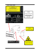
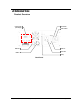
2. INTRODUCTION Product Overview Control Panel (LED display) Fuse holder Power Switch DMX Out Power In Power Out DMX In Safety Back Panel Scorpion™ GVC/RVM/RGY User Manual (Rev.
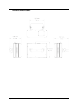
Product Dimensions Page 10 of 26 Scorpion™ GVC/RVM/RGY User Manual (Rev.
3. SETUP AC Power This product has an auto-ranging power supply and it can work with an input voltage range of 100~240 VAC, 50/60 Hz. To determine the power requirements for a particular fixture, see the label affixed to the back plate of the fixture or refer to the fixture’s specifications chart. A fixture’s listed current rating indicates its average current draw under normal conditions.
Mounting Orientation The Scorpion™ GVC/RVM/RGY units may be mounted in any position, provided there is adequate room for ventilation. Rigging Be sure that the structure onto which you are mounting this product can support its weight. Please see the “Technical Specifications” section of this manual for weight information. Mount the fixture securely. You can do this with a screw, a nut, and a bolt. You could also use a mounting clamp if rigging this product onto a truss.
Proper Usage This fixture is for overhead mounting only. For safety purposes, CHAUVET® recommends mounting your lighting effect fixtures on steady elevated platforms or sturdy overhead supports using suitable hanging clamps. In all cases, you must use safety cables. You can obtain appropriate mounting hardware from your lighting vendor. International laser safety regulations require that laser fixtures must be operated in the fashion illustrated below, with a minimum of 3 meters (9.
4. OPERATION Control Panel Operation To access the control panel functions, use the four buttons located underneath the display.
Menu Options The menu below refers to three different CMY products, GVC, RVM, and RGY, each with a different set of colors.
Configuration DMX Mode Setting this product to operate in DMX mode will allow you to control it with a DMX controller. 1) Connect this product to a suitable power outlet. 2) Turn this product on. 3) Connect a DMX cable from the DMX output of the DMX controller to the DMX input socket of this product. Starting Address When selecting a starting DMX address, you must always consider the number of DMX channels assigned to the selected DMX mode.
Automatic Mode To enable the Automatic mode, follow the instructions below: 1) Press
Master/Slave Mode This mode allows a single Scorpion™ GVC/RVM/RGY fixture (the “master”) to control the actions of one or more Scorpion™ GVC/RVM/RGY units (the “slaves”) without the need of a DMX controller. The master unit will be set to operate in either Automatic, Sound, or Laser Sky mode, while the slave units will be set to operate in Slave Mode. Once set and connected, the slave units will operate in unison with the master unit. Configure the units as indicated below.
DMX Channel Assignments and Values Channel Function Value Setting 1 Control Mode (Use channels 2~10 in this mode) 000 018 036 054 072 090 108 126 144 162 180 198 216 234 2 Pattern selection (Only when CH1 is between 000~017) 000 255 32 patterns, as shown in page 20 000 025 050 075 100 125 150 175 200 225 000 005 000 128 170 210 017 035 053 071 089 107 125 143 161 179 197 215 233 255 024 049 074 099 124 149 174 199 224 255 004 255 127 1
DMX Ch.2 Pattern Selection DMX VALUE Page 20 of 26 PATTERN DMX VALUE PATTERN DMX VALUE 000~007 096~103 190~197 008~015 104~111 198~205 016~023 112~119 206~213 024~031 120~127 214~221 032~039 128~135 222~229 040~047 136~143 230~237 048~055 144~151 238~245 056~063 152~159 246~255 064~071 160~167 072~079 168~175 080~087 176~181 088~095 182~189 PATTERN Scorpion™ GVC/RVM/RGY User Manual (Rev.
5. TECHNICAL INFORMATION Fixture Maintenance Dust build up reduces light output performance and can cause overheating. This can lead to reduction of the light source’s life and mechanical wear. To maintain optimum performance and minimize wear, you should clean your lighting fixtures at least twice a month. However, be aware that usage and environmental conditions could be contributing factors to increase the cleaning frequency.
General Troubleshooting Symptom Circuit breaker or fuse keeps blowing Product does not power up Possible Cause Possible Action • Excessive load on the circuit • Make sure that the total load does not exceed 80% of the breaker or fuse nominal current • Short circuit along the power lines • Check the power lines and power cords • No energy on power outlet • • Check power outlet Change to another outlet • Loose or damaged power cord • Check the power cord • Blown fuse • Replace blown fu
Returns Procedure The user must send the merchandise prepaid, in the original box, and with its original packing and accessories. CHAUVET® will not issue call tags. Call CHAUVET® and request a Return Merchandise Authorization (RMA) number before shipping the fixture. Be prepared to provide the model number, serial number, and a brief description of the cause for the return. The user must clearly label the package with a Return Merchandise Authorization (RMA) number.
DMX Primer The USITT DMX512-A data transmission protocol (DMX, from now on) is based on the EIA-485 standard and it has 512 channels (001 to 512). This system requires a controller (DMX controller), one or more DMX compatible fixtures, and a DMX circuit (also known as “DMX universe”) to link the fixtures to the controller. Depending on their complexity and features, DMX compatible fixtures may require from one to more than 30 DMX channels to operate.
DMX Cabling The DMX protocol requires using special data cables to accommodate for the high speed digital signals it uses. Despite their apparent similarities, data cables are electrically different from standard microphone cables because they can carry high frequency digital signals and have better protection against electromagnetic interference. You can purchase CHAUVET® certified DMX cables directly from a dealer/distributor or make your own DMX cable.
6. TECHNICAL SPECIFICATIONS Dimensions and Weight Length 11 in (276 mm) Width 8.5 in (215 mm) Height 7.4 in (187 mm) Weight 5.6 lbs (2.7 kg) Note: Dimensions in inches rounded to the nearest decimal digit Power Power Supply Type Switching (internal) Range 100~240 V, 50/60 Hz Voltage Selection Auto-ranging Parameter Energy consumption Operating current (units) Power linking (units) Fuse 120 V, 60 Hz 22 W 0.2 A 14 units F 1 A, 250 V 230 V, 50 Hz 22 W 0.