TFX-D12 Stage Dimmer™ 12 USER MANUAL 1 2 CH.DIGIT ALMODULEDIMMER TM STAGE DIMMER 12 MENU UP DOWN DMX ESC Chauvet, 3000 N 29th Ct, Hollywood, FL 33020 U.S.A (800) 762-1084 – (954) 929-1115 FAX (954) 929-5560 www.chauvetlighting.
TABLE OF CONTENT TABLE OF CONTENT........................................................................................................................................................... 2 BEFORE YOU BEGIN........................................................................................................................................................... 3 WHAT IS INCLUDED .................................................................................................................................
BEFORE YOU BEGIN What is included ¾ ¾ ¾ 1 x Stage Dimmer™ 12 (TFX-D12) Manual Warranty Card Unpacking Instructions Immediately upon receiving a fixture, carefully unpack the carton, check the contents to ensure that all parts are present, and have been received in good condition. Notify the shipper immediately and retain packing material for inspection if any parts appear damaged from shipping or the carton itself shows signs of mishandling. Save the carton and all packing materials.
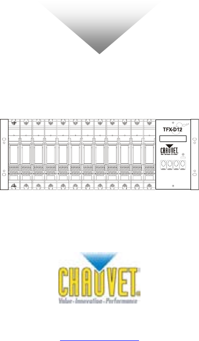
Introduction Product Overview LCD Display 10A Circuit breaker DMX Signal Indicator Forced air cooling MENU Button UP Button Modular dimmer module DOWN Button Standard 19” EIA rack mountable ESC Button Carrying handles Module air intake I/O Panel 2 CH.
INSTALLATION Mounting The TFX-D12 dimmer packs are designed to be mounted in a standard 19” EIA rack using the two mounting holes on each flange/(ears). The two mounting flanges are designed for securing the dimmer pack to the front rack mounting rails. It is highly recommended that you add support to the rear of the dimmer pack, especially in touring or road case environments. The TFX-D12 depends on forced air cooling and the following guidelines should be applied during installation: 1.
Operating Instructions Power Connections Warning! Make certain that power is removed from the circuits before you begin installation of the dimmer. Consult your local electrical codes to determine the proper wire type and wiring methods for your regional installation.
Output Power LOADING CH12 CH11 E CH10 CH9 E CH8 CH7 E CH6 CH5 N E CH4 CH3 E CH2 CH1 E L3 L2 N N E E L1 Control Wiring D MX512 Input: 3-pin XLR (male) Output: 3-pin XLR (female) Pin Signal 1 DGND 2 DATA ( - ) 3 DATA ( + ) ANA LOG 0- 10 VDC Input: 15-pin M D-Sub Pin Signal 1 Channel 1 2 Channel 2 3 Channel 3 4 Channel 4 5 Channel 5 6 Channel 6 7 Channel 7 8 Channel 8 9 Channel 9 10 Channel 10 11 Channel 11 12 Channel 12 13 NC 14 NC 15 Ground TFX-D12 U
OPERATING INSTRUCTIONS Start Menu Upon powering the dimmer, the LCD panel will display the software version presently installed and shortly after, will enter standby mode. First line displays dimming levels of each channel. 1 2 3 4 5 6 7 8 9A B C Second line displays the channel. A~C = 10~12 Menu Navigation 1 2 3 4 5 6 7 8 9A B C Dmx fail Hold Analog Prog.
Operating Instructions Setup Menu Action 1) Press the MENU button to enter the setup menu. 2) There are 6 menu items to choose from; Dmx fail, Phase Correction, Dmx addr, Preheat, Curve and Preset. 3) Press the UP and DOWN buttons to scroll menu items. 4) Press ESC to exit the setup menu. Dmx fail DMX Fail [Dmx fail] The DMX Fail feature allows the user to select how the dimmer will behave if you were to loose the DMX controller’s signal to the dimmer.
Operating Instructions Phase Correction [Pha corr] Action 1) Press the MENU button to enter the setup menu. 2) Press the UP/DOWN buttons until you reach [Pha corr]. 3) Press MENU to enter the sub-menu. 4) Press UP/DOWN buttons to choose between Yes and No. 5) Press ESC button to activate. Pha corr (Yes) or (No) DMX Address [Dmx addr] Action 1) Press the MENU button to enter the setup menu. 2) Press UP/DOWN buttons to choose between [Block] and [Single] configuration.
Operating Instructions Preheat [Preheat] Action 1) Press the MENU button to enter the setup menu. 2) Press the UP and DOWN buttons to scroll menu items until you reach [Preheat]. 3) Press MENU button to enter the sub-menu. 4) Press the UP/DOWN buttons to choose between [All] and [Chan]/Single Channel mode. 5) Press MENU to select mode. A L L [ A l l] 1) Preheat All Chan [1] [000%] All [005%] Press UP/DOWN to select the preheat value between [000%] – [050%] for all channels.
Operating Instructions Preset [Preset] Action Preset 1) Press the MENU button to enter the setup menu. 2) Press the UP and DOWN buttons to scroll menu items until you reach [Preset]. 3) Press the MENU button to enter the submenu. 4) Press UP/DOWN buttons to select between All/Single Channel mode. A L L [ A l l] 1) All [000%] Press UP/DOWN to select the master dimmer level value between [000%] – [100%] for all channels.
APPENDIX DMX Primer There are 512 channels in a DMX-512 connection. Channels may be assigned in any manner. A fixture capable of receiving DMX 512 will require one or a number of sequential channels. The user must assign a starting address on the fixture that indicates the first channel reserved in the controller. There are many different types of DMX controllable fixtures and they all may vary in the total number of channels required. Choosing a start address should be planned in advance.
Appendix Maintenance To maintain optimum performance and minimize wear fixtures should be cleaned frequently. Usage and environment are contributing factors in determining frequency. As a general rule, fixtures should be cleaned at least twice a month. Dust build can cause overheating. Be sure to power off fixture before conducting maintenance. Unplug fixture from power. Use a vacuum or air compressor and a soft brush to remove dust collected on external vents and internal components.
Appendix Technical Specifications WEIGHT & DIMENSIONS Length......................................................................................................................... 451 mm (17.75 in) Width ............................................................................................................................ 495 mm (19.5 in) Height .................................................................................................................................178 mm (7 in) Weight ......