ShowXpress User Guide th 3000 N 29 Court Hollywood, FL 33020 (800) 762‐1084 | Phone (954) 929‐5560 | Fax www.chauvetlighting.
TABLE OF CONTENTS BEFORE YOU BEGIN ........................................................................................................................................................... 3 INTRODUCTION ................................................................................................................................................................... 4 XPRESS™ 100 FEATURES ......................................................................................................................
2D VIEW ..................................................................................................................................................................... 59 3D VIEW ..................................................................................................................................................................... 59 OPERATING INSTRUCTIONS ......................................................................................................................................
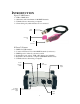
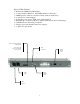
INTRODUCTION Xpress™ 100 Features ¾ ¾ ¾ ¾ USB to DMX cable 10 fixtures with a maximum of 100 DMX channels Unlimited shows when using a computer 3D rendering only while interface is not connected DMX output Protective cap USB connection X-Factor™ Features ¾ ¾ ¾ ¾ ¾ ¾ DMX-512 USB interface Connect 2 X-Factors™ for 1024 DMX channels (2 universes) DMX input for on-the-fly, external override Selectable power options: USB or DC adaptor (not included) Playback 1 show without a computer (100 DMX channels max)
Xpress™ Plus Features ¾ ¾ ¾ ¾ ¾ ¾ ¾ ¾ ¾ Rackmount DMX-512 USB interface Connect 2 Xpress Plus™ for 1024 DMX channels (2 universes) DMX input for on-the-fly, external override (works in stand-alone) Connector for external triggers Selectable power options: USB or AC (cable included) Playback up to 14 shows without a computer (with speed control and layering) Unlimited shows when using a computer Trigger scenes automatically without a computer 1-space (1U) rack mount Used for external triggering of light sc
SETUP CPU Requirements MINIMUM HARDWARE REQUIREMENTS (without 3D visualization) ¾ ¾ ¾ ¾ ¾ Pentium 1Ghz with 512MB RAM under Windows® XP (32-bit only) Pentium 2Ghz with 1GB RAM under Windows® Vista (32-bit only) 100MB of hard disk space 1 CD-ROM drive 1 USB port MINIMUM HARDWARE REQUIREMENTS (with 3D visualization) ¾ ¾ ¾ ¾ All requirements above ATI Radeon™ 7000 or NVIDIA® GeForce2 (gobo viewing disabled) ATI Radeon™ 9000 or NVIDIA® GeForce4 (maximum 3D rendering) Desktop colors set to 32 bits Software I
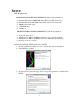
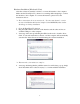
4. Choose the installation directory to install ShowXpress™. The default location is C:\Program Files\ShowXpress and usually does not need to be altered. 5. Select a name and location for Windows® to place the Start Menu folder. 6. Check the box titled “Create a desktop icon” if you want a folder to be created on your desktop. This action cannot be undone so it may be better to create the folder and delete it later on. Click NEXT.
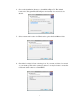
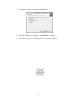
7. Confirm the settings and then click INSTALL. 8. After the installation completes, click FINISH to confirm. ¾ You must be logged in as Administrator to install the software.
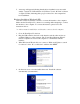
Hardware Installation (Windows® Vista) After the software is installed, it is time to connect the interface to the computer. Make sure the ShowXpress™ software is not running while attempting to connect the interface to the computer. To connect the interface, please follow the instructions below: ¾ These instructions do not account for the “User Account Control” security measure that Windows® Vista has. Simply click CONTINUE if that window should appear during installation. 1.
5. A message will appear indicating that the driver installation was successful and the “stand alone” LED will turn off (X-Factor™) and “PC Link” will turn on (Xpress™ Plus) indicating that a proper connection to the computer has been established. Hardware Installation (Windows® XP) After the software is installed, it is time to connect the interface to the computer. Make sure the ShowXpress™ software is not running while attempting to connect the interface to the computer.
5. Windows® will then ask for a specific place to install the drivers from. Click BROWSE and direct the driver path to the C:\WINDOWS\system32\drivers folder and select the “CyUsb” driver. Click OPEN and then OK on the following screen to start the installation. ¾ Substitute the driver “FTD2XX” for “CyUsb” if connecting an Xpress™ 100. 6.
Driver Reinstallation (Windows® Vista) If the driver installation fails or you need to reinstall the driver for any reason, the driver can be installed manually. Please follow the instructions below: 1. Click START > CONTROL PANEL > SYSTEM > DEVICE MANAGER to access the hardware devices on your computer. 2. Extend the “Universal Serial Bus Controllers” section by clicking on the small square to the left. 3. Highlight the “BOX Interface (version x.
3. Highlight the “BOX Interface (version x.xx)” (or “USB Plus interface) and select “uninstall” on the top menu bar. This will uninstall all associated drivers for the interface. 4. Click “scan for hardware changes” also on the top menu bar to have the computer auto-detect any new hardware. 5. Repeat the same steps from “Hardware Installation (Windows® XP) to install the driver again. 6.
USING SHOWXPRESS™ Initial Parameters (Init_param) When the CONTROL_BOARD is opened for the first time, you must first select the operating language for the software and the manual. Simply click on the flag that corresponds to the desired language. This can be changed later for multilingual users. Close the INIT_PARAM window and re-open the CONTROL_BOARD. This time it will open in the language that was just selected, and will also read “USB X-Factor interface ok.
CONTROL BOARD Every screen (except Stand Alone) is initialized from the CONTROL_BOARD and it must also be running in the background in order to correctly send and receive DMX signals. It will display the installed software version and it will also list any connected interfaces on separate lines. Since this is the software’s main point of access, it cannot be minimized to the task bar or maximized to fill the entire screen. You can, however, drag and drop it to a secondary monitor.
FIXTURE The FIXTURE screen is the window that assigns DMX addresses to the fixtures of a show, creates and edits new and existing fixture profiles, assigns group letters and 3D settings, and finally sets the level (or value) of each DMX channel.
Here is a list of the buttons within this screen and their function. BUTTONS DESCRIPTION Closes the screen. Creates an empty workspace for a new, custom fixture. 1) Saves a custom fixture’s settings and moves it to the “Personal Fixtures” window. 2) Drops a fixture from the “Personal Fixtures” to the “DMX Addressing” window. 1) Adds channels to a new, custom fixture under the CHANNELS column. 2) Adds values to specific channels under the LEVELs column.
Creating New Fixtures 1. Click the icon to make a clean working space for the new fixture. 2. Type a name for the fixture where it says “NEW_FIXTURE” 3. Define its 3D properties by choosing whether it is a moving yoke, moving yoke wash, mirror, etc. Once that has been chosen, other options may become available. Enter the required information for the new fixture. 4. Click the icon for each channel of DMX that the fixture requires. For example, if it is a 5-channel scanner, click the icon five times.
DMX Addressing Procedures The fixtures in the “DMX addressing” window are the fixtures that are going to be used in a show. When they are added from the “Personal Fixtures” they will automatically be given a DMX address based on the quantity of channels used by the fixture before it. These DMX addresses may be manually adjusted as needed. ¾ When no fixtures are present in the “DMX addressing” window, it will automatically start the first fixture at DMX address of 001.
BUILDER The BUILDER screen is the window that allows for fixture programming, editing steps and step time, saving light scenes, and activating some built-in movement macros. (Just to name a few!) Before immediately diving into the software, understanding the lingo will drastically save time when trying to program for the first time. Opposite of a lot of physical DMX controllers, ShowXpress™ uses the same terminology but in a different way.
Step Area The “step area” shows the number of total steps in a specific light scene, the duration of the entire show and of a specific step, and allows for editing of existing steps and creating new ones. STEP AREA BUTTONS DESCRIPTION Displayed when a step cannot be deleted. Only occurs when there is a single step in any scene. Copies any step and puts it into the computer’s memory. Pastes a copied step in front of the one that is currently showing. Adds a step to the current scene.
Scene Area The “scene area” gives access to all programmed scenes, typing names to new scenes, inserting scenes into each other, saving scenes and deleting them as well. SCENE AREA BUTTONS DESCRIPTION Plays the current scene. (All other functions will be disabled until stopped.) 1) Allows to manually enter a name for a new scene or rename a previously recorded scene. 2) Gives access to all previously recorded scenes. Creates a new, empty scene.
Mouse Area The “mouse area” displays the position of the mouse coordinates using both DMX values (0 – 255) and percentages (0 – 100%) and scrolls through all fixtures using the arrows on the sides. Shows the percentage of the pan and tilt. Scroll the visible channels to the left Shows the DMX values of the pan and tilt. Scroll the visible channels to the right.
Miscellaneous Area The “miscellaneous area” activates the 2D View, 3D View, activates or terminates the DMX signal coming from the computer, allows to undo a mistake and activates the “mask” feature. MISC. AREA DESCRIPTION BUTTONS This is a scene that can only contain a single step and is designed to be added over the current scene playing back.
Override Area The “override area” allows for additional control of a single channel or multiple channels. Time-saving icons include “set value on all steps,” “set fade on all steps,” copy and paste functionality and “cut” (not delete). OVERRIDE AREA BUTTONS DESCRIPTION Deactivates a channel from a specific step and sets its value to OFF, not 000. This will prevent accidental overriding when using the LIVE screen. Copies a channel’s value and puts it into memory.
DMX Channels Area The “DMX channels area” provides the way to control all fixtures connected to the interface using a series of sliders. The icons above the channels are the same ones that are in the FIXTURE screen and offer an easy way to select multiple channels for simultaneous programming. The names and group letters are also displayed along with the DMX channel under each fader. There are many parts of the “DMX channels area” that when combined together create a very powerful light-programming tool.
Activated vs Non-Activated Faders There is a big difference in how scenes are played back based on if a specific channel has been “activated” or not. Non-activated faders will show a DMX channel beneath the slider (example below shows 13). Once the fader becomes activated, it will show one of the fade styles. When multiple scenes are played back in the LIVE screen, it layers (or stacks) the scenes on top of another and the last scene to be triggered will take priority.
Right-Clicking There are a few additional menus that become accessible when clicking with the right mouse button. The list below explains how to access these hidden menus and what their functions are. 1. When the icon above the channel slider is an “X” or “Y” (pan or tilt), right-click it to access a hidden menu that allows to load, save or reverse movements, shift movement one step forward or backward and it enables the “F4” key to resize the movement.
2. When the icon above the channel slider is a color or gobo wheel, rightclick it to access all of the color and gobo possibilities of that particular fixture. Simply click the color or gobo and the light fixture will instantly jump to it.
Display Window The display window has a few different functions depending on the fixtures that are being used. 1. When the fixture has pan and/or tilt channels, programming on a 2D drawing board can be accomplished simply by clicking the fader that corresponds to the pan and/or tilt. This will also give access to the function keys which allow the programmer to change the look of the drawing board to something different. Please read below for more details about the function keys.
2. When the icon above the channel slider changes to look like this icon, it means that channel can now controlled by using the color mixing palette. Displays the actual color emitted from the RGB color‐mixing fixture. Copies the selected panel color to memory. Pastes memorized color from memory. Adjusts the brightness of the output. Move the mouse over this area to select the color.
GENERATOR This window contains some of the newest technology in the lighting controller market and allows the programmer to quickly and easily generate movement and basic curve macros with delay effects in a matter of seconds. This technology is seen in larger concert-style control desks and is also available in ShowXpress™. There are two different functions of the GENERATOR window. The first is a movement macro creator which incorporates only the pan and tilt channels for all moving head and scanners.
Creating Movement Macros To create movement macros with delay effects, please follow these steps: 1. Click GENERATOR on the CONTROL_BOARD to open the window. 2. Open the BUILDER screen also from the CONTROL_BOARD and select the group of fixtures you wish to make a movement macro with. 3. That group now shows up in the GENERATOR window and lists the group letter and the quantity of fixtures within it. (This example selected group “d” and it contains 2 fixtures.
¾ These can also be opened, edited and resaved for future use. ¾ Placing the mouse over a red dot will display the pan (first number) and the tilt (second number) of that specific point. 6. Click the PLAY icon to start the playback and then click the DMX icon to send the data through the interface to the fixtures. The selected fixtures will now begin moving based on the movement and speed that was entered. 7.
Creating Curves To create basic curves with delay, please follow these steps: 1. Click GENERATOR on the CONTROL_BOARD to open the window. 2. Open the BUILDER screen also from the CONTROL_BOARD and select the group of fixtures you wish to make a movement macro with. 3. That group now shows up in the GENERATOR window and lists the group letter and the quantity of fixtures within it. (This example selected group “d” and it contains 2 fixtures.
¾ A fan setting of “0” will result in all fixtures moving to the exact same spot at the exact same time with no delay. 9. Click the GENERATE icon to save the curve as a scene (.SCE). This file is immediately ready for editing in the BUILDER window. 10. Open the new scene from BUILDER, make any changes or additions (such as movement) and save again. The scene is now complete. The “curve style” (points, lines or curves) changes the display to reflect how the movements and curves are seen. 1.
Example This example demonstrates what the screens should look like when creating a scene with pan/tilt movements, color chasing and keeping the shutter/dimmer open throughout the entire scene. This first step shows that the pan, tilt, color, dimmer and shutter are all selected to be a part of the scene. When the channel is highlighted in blue (pan/tilt), the window to the right will change to reference its steps within the scene. Each of the red dots indicates a movement step.
This third and fourth image show the level (or value) of the dimmer and shutter. Right-click on any dot to access another menu which will allow to edit the points. Changing Groups To change the fixture group that you are working with, please follow the steps below: 1. Click the padlock icon to unlock the window. 2. Go back to the BUILDER screen and select another keyboard group or select the fixtures on the fly by using the 2D VIEW. 3.
TIMELINE TIMELINE allows the programmer to create shows by synchronizing lighting, audio, video and still pictures together by using drag and drop technology. ¾ The LIVE screen must be open for TIMELINE to playback correctly. The “Light scenes” window displays a list of all scenes created from the BUILDER screen. These scenes are ready to be dragged into a new or saved timeline file. The “Multimedia files” list shows all imported sound, video and still images that are a part of the show.
Adding Multimedia Files To add multimedia files to the list, please follow the directions below: 1. Click the “import multimedia files” icon directly under the “Multimedia files” heading. Import multimedia files Remove multimedia files Shows the full path (location) of the multimedia files on your computer. 2. Direct ShowXpress™ to the location of the audio, video and/or image files and click OPEN. Repeat this process as much as necessary. ¾ These files will available until the current project is closed.
Creating a Timeline To create a new timeline from scratch, please follow the directions below: 1. Click TIMELINE on the CONTROL_BOARD to open the window. 2. Click to start with a fresh palette. 3. Enter the amount of time for the timeline and type it in the text box where it says “Timeline duration.” 4. Enter the amount of lighting timelines to have within the file from 1 to 10. This can be changed at any time. 5. Click OK to save the settings of the new timeline.
Digital timeline used to sync files to each other. The green dot shows the location that is currently playing back. Click and drag this marker to start the playback from any point. Set the red dot to any spot within the timeline to automatically start playback when the Video file is clicked.
LIVE LIVE screen is the application that plays back the pre-programmed light scenes by layering them. Please refer to the glossary for a definition of layering. LIVE is designed to use in a live situation where the software will be manned throughout the entire show.
There are a few buttons that can be found within the LIVE screen. These buttons are: LIVE DESCRIPTION BUTTONS This sets the board to allow you to select the next scenes you want by deactivating the button without actually deactivating the scene. While scenes are playing back, click this button and then click the scenes that are currently playing and then click scenes that you want to playback next.
Right-click any scene to access a menu which will allow you to: 1. 2. 3. 4. 5. 6. 7. 8. Move a button – moves a scene within the page.
Adding a Scene 1. Right-click on the top of the page (in the tab area) that you wish to add a file to and select the appropriate option. To add a light scene, click “add light scene,” to add a Timeline file click “add Timeline,” and to add an audio, video or still image click “add multimedia.” 2. Direct the software to the file’s location and click OPEN. ¾ Multiple files may be added simultaneously by using a combination of the CTRL and SHIFT keys.
Importing a Picture 1. Take a picture of the desired location and import that picture to your computer using any method you are familiar with. Make sure to store this picture in a location you will remember. 2. Right-click anywhere in the 2D VIEW and select CHANGE BACKGROUND. 3. Point the software to the location of an image you wish to import and click OPEN. ¾ You can also change the picture of the fixture by right-clicking the actual fixture and choosing “change fixture picture.
SCREEN CONTROL This window will remain dormant on the computer until a multimedia file is played back from either LIVE or TIMELINE. SCREEN CONTROL is the same as Windows® Media Player, iTunes™ or any other multimedia playback program, and even uses the same codecs as these third-party programs. ¾ To activate SCREEN CONTROL, a multimedia file must be played in either LIVE or TIMELINE first, and then the icon will appear.
5. Stop – immediately stops the playback of the selected multimedia file but does not close the window 6. Exit – closes the window and removes the icon from the taskbar Menu Option Sub-Function Description Removes the Windows® border and prevents you from accidentally closing or minimizing the window Keeps SCREEN CONTROL on top of all other windows Forces the window to a fixed position within the monitor’s resolution Will output the multimedia files to a secondary monitor.
3D VIEW This window shows a representation of a show in three dimensions. It incorporates most aspects of any environment including people, truss, speakers, lighting fixtures and stages. Each object can later be manipulated and placed anywhere within the window to copy any setting or to create a new one. Once the 3D View is set up and everything is in the proper place, programming can be done offsite and still be able to see if the show is going to look good.
Stage Settings The “Stage settings” allows editing all aspects of the stage including dimensions, brightness, textures of walls, floor and ceiling, etc. Set the unit of measurement to either meters or feet Adjust the overall brightness of the 3D View Type in the exact numbers for the width, height and depth of the 3D View Check the boxes to the walls you want to show.
Object Settings The “Object settings” allows adding and editing objects within the 3D View such as the position, orientation, scale and color. By selecting the objects in the 3D View and then using the mouse, the objects can be moved around freely without having to slide the faders listed below. 1. Position – allows to move an object on its X, Y and Z axis by sliding the three bars on the bottom of the window 2.
Fixture Settings The “Fixture settings” allows editing the fixtures within the show such as the position, orientation, scale and color. Much like the “Object settings,” the “Fixture settings” allows editing and manipulating each fixture individually.
3D Settings The “3D Settings” allows editing all aspects relating to the 3D performance of the window.
DMX INPUT DMX INPUT connects the interface (X-Factor™ or Xpress™ Plus only) to an external controller. When connected to an external controller and correctly patched (see glossary for definition), the faders will be able to override the settings of the show that is playing back. This is very useful because it allows the playback operator to manually alter the show without changing the actual programming. ¾ The X-Factor™ interface must be connected to a computer in order to link with an external controller.
BACKUP BACKUP exports the current settings and saves them for future reference. There is no limit to the amount of backups the user can create (unless there is no space available on the hard disk). ¾ This does not save multimedia files! Please make sure to save these files separately! To backup or export a show, follow these instructions: 1. 2. 3. 4. Open the CONTROL_BOARD and click BACKUP. Enter a name that will describe the show. Click BROWSE to select a location to save the backup file.
RESTORE RESTORE will restore a show (or a part of it) as many times as needed. To restore or import a show, follow these instructions: 7. Open the CONTROL_BOARD and click RESTORE. 8. Click BROWSE and find select the folder that contains the information 9. Select any and all check boxes that you wish to import. If the check box is selected, it will overwrite those settings. ¾ This will not restore multimedia files from TIMELINE or LIVE! ¾ Be sure to have a backup of the files you are writing over! 10.
STAND-ALONE STAND-ALONE is the link between the computer and the interface when trying to upload lighting scenes to run without a computer. ¾ The interface(s) must have a successful connection to the computer in order to upload the scenes. The X-Factor™ can store a single scene without a computer and the Xpress™ Plus can store up to 14. ¾ No scenes can be uploaded to the Xpress™ 100 interface. To upload lighting scenes to the interface(s), please do the following: 1.
Tips & Tricks The “Tips & Tricks” section is designed to give a little more insight into each of the ShowXpress™ screens and even offer some tricks with navigating around from screen to screen. ¾ These tips and tricks may not apply to all software versions. ¾ Please visit our website’s “download” section for tutorials about each window. TIMELINE 1. When multimedia files are placed over each other, the one on top will take priority. 2.
processing power the computer will use to move about 3D VIEW. Make sure not to go overboard with the details! 3. Custom gobos can be added and seen in 3D VIEW and FIXTURE by making them specific sizes and formats. Please see the online forum for more details. 4. The following 3D object is special: "_special\matrix_panel.obj". It shows the video coming from the screen MATRIX VIEW.
Operating Instructions This section is a quick “how to” area about the key windows of ShowXpress. Building a scene 1. Open BUILDER and name the scene you wish to program by entering a name in the text box under the “scene area.” 2. Trigger the fixture group(s) by selecting the keyboard letter. These fixtures now have a pink bar across the top of their channels. 3. Slide the faders to their appropriate positions for the step and then change the step time (if needed) to the appropriate amount of time. 4.
Glossary Below is a list of common terms found throughout this manual and lighting in general. 1. Blackout – an action that instantly douses all output; usually by pressing a single button. 2. CMY – a subtractive color mixing process that combines cyan, magenta and yellow filters to create other colors in the spectrum. These secondary colors of light at 100% will produce black, or the absence of light. 3.
f) MP3 (MPEG-1 Audio Layer 3) – a digital audio encoding format using a form of data compression. It is the common audio format for consumer audio storage. g) MPEG (Moving Picture Experts Group) – a working group of technicians in charge of the development of video and audio encoding standards. h) OGG – is a free, open standard format and is unrestricted by software patents and is designed to provide for efficient streaming and manipulation of high quality digital multimedia.
19. Daisy chain – a wiring practice in which device A is connected to device B, device B is connected to device C, device C is connected to device D, etc. each device in the chain carries the same information from device to device. The last device receives the exact same information as the first device. 20. Laser (Light Amplification by Stimulated Emission of Radiation) – emits light in a narrow, single-colored beam with a well-defined wave length. 21.