
Data Sheet


Série MN
Pinces ampèremétriques pour courant AC
Non-contractual document
906200083 - Ed 1
12.07 (1/4)
PAC Series
AC/DC current clamp
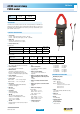
DESCRIPTION
The PAC27 model accurately measures AC or DC currents by making use of the Hall effect
principle. This clamp with mV output on BNC (direct reading on oscilloscopes, etc.) is
equipped with an automatic DC zero system and a deactivatable Auto Power Off (APO) function.
It can be powered by a standard mains power pack via a Micro USB connector.
•
Bandwidth:
DC .. 30 kHz (-3 dB) (depending on current value)
•
Rise time (10 to 90 % of Vs)
≤ 11 µs
•
Fall time (90 to 10 % of Vs)
≤ 11 µs
•
10 % delay time:
≤ 10 µs
•
Insertion impedance:
0.05 mΩ @ 400 Hz, 3.4 mΩ @ 10 kHz
•
Maximum currents:
3,000 A DC or 1,000 A AC permanent for a
frequency < 1 kHz (limitation proportional to the
reciprocal of one third of the frequency beyond that)
•
DC zero adjustment:
150 A & 1,400 A calibres:
Automatic, by 40 - 60 mA increments
•
AC noise output:
150 A calibre: ≤ 3 mV or 0.3 A peak-peak
1,400 A calibre: ≤ 1 mV or 1 A peak-peak
•
Power supply:
9 V alkaline battery (NEDA 1604A, IEC 6LR61)
5 V DC Micro USB type B
•
Battery life:
50 hours typical
•
Consumption:
10 mA typical (battery)
31 mA typical (µUSB 5V)
•
"ON" LED:
"Lit" = In operation & battery level OK
"Flashing" = remaining battery life < 4 hours
"Colour = green" = APO ON
"Colour = yellow" = APO OFF
•
"OL" LED:
Overload indication: current measured too high for
the calibre used
•
In uence of power supply voltage:
None
•
In uence of temperature:
≤ 3 % variation over the whole operating
temperature range
•
In uence of relative humidity:
≤ 0.5% from 10 % to 85 % RH at room
temperature
•
In uence of an adjacent conductor carrying a
50 Hz alternating current, 23 mm away from the
clamp:
< 10 mA/A
•
In uence of a 400 A/m external eld @ 50 Hz:
< 1.3 A
•
In uence of the position of a Ø 20 mm conductor
in the jaws:
≤ 0.5 %
•
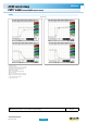
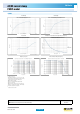
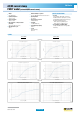
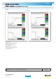
In uence of the frequency
(4)
:
150 A calibre:
10 Hz .. 400 Hz: ≤ 1 % of V
S
400 Hz .. 7 kHz: ≤ 3.5 % of V
S
7 kHz .. 30 kHz: see curve
1,400 A calibre:
10 Hz .. 400 Hz: ≤ 1 % of V
S
400 Hz .. 10 kHz: ≤ 3.5 % of V
S
10 kHz .. 30 kHz: see curve
•
Common mode rejection:
> 65 dB A/V @ 50 Hz
•
Remanence:
0 to 100 A DC: 2.8 A typical
0 to 200 A DC: 3.5 A typical
0 to 400 A DC: 5 A typical
0 to 800 A DC: 5.3 A typical
0 to 1,200 A DC: 5.7 A typical
0 to 1,400 A DC: 5.8 A typical
MECHANICAL SPECIFICATIONS
•
Maximum jaw opening:
39 mm
•
Clamping capacity:
Cables: Ø 39 mm
Ø 25.4 mm x 2
Busbars: 1 bar 50 x 12.5 mm
2 bars 50 x 5 mm or 31.5 x 10 mm
3 bars 25 x 8 mm
4 bars 25 x 5 mm
•
Output:
2 m coaxial cable terminated by an isolated BNC
plug
•
Dimensions:
236.5 x 97 x 44mm
Current
100 A AC
150 A DC
1,000 A AC
1,400 A DC
Output
10 mV/A 1 mV/A
ELECTRICAL SPECIFICATIONS
•
Current calibre:
0.2 A AC .. 100 A AC (150 A peak) / 0.4 A DC .. 150 A DC
0.5 A AC .. 1,000 A AC (1,400 A peak) / 0.5 A DC ..1,400 A DC
•
Output signal:
10 mV AC+DC / A AC+DC (1.5 V for 150 A)
1 mV AC+DC / A AC+DC (1,4 V for 1,400 A)
•
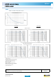
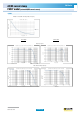
Accuracy and phase shift
(1)
:
Calibre 150 A
Primary current 0.5 A .. 1 A 1 A .. 40 A 40 A .. 100 A
100 A .. 150 A
(DC only)
Accuracy in % of output signal ≤ 3% + 5 mV ≤ 3% + 5 mV ≤ 1.5% ≤ 1.5%
Phase shift
(2)
Not specified ≤ 2° ≤ 2° -
1,400 A calibre
Primary current 0.5 A .. 3 A 3 A .. 100 A 100 A .. 200 A 200 A .. 800 A 800 A .. 1,000 A
1,000 A .. 1,400 A
(DC only)
Accuracy in % of output signal ≤ 1.5% + 1 mV ≤ 1.5% + 1 mV ≤ 2.5% ≤ 2.5% ≤ 4% ≤ 5%
Phase shift
(3)
Not specified ≤ 2° ≤ 2° ≤ 1.5° ≤ 1.5° -
Modèle PAC27 (Isolated AC/DC current sensor)