DÉTECTEUR DE TENSION VOLTAGE DETECTOR SPANNUNGSPRÜFER RIVELATORE DI TENSIONE DETECTOR DE TENSIÓN C.A 742 C.
English ................................................ 20 Deutsch .............................................. 38 Italiano ................................................ 56 Español .............................................. 74 Vous venez d’acquérir un détecteur de tension C.A 742 ou C.A 742 IP2X et nous vous remercions de votre confiance. Pour obtenir le meilleur service de votre appareil : lisez attentivement cette notice de fonctionnement, respectez les précautions d’emploi.
PRÉCAUTIONS D’EMPLOI Cet appareil est protégé contre des tensions n’excédant pas 600 V par rapport à la terre en catégorie de mesure IV. La protection assurée par l’appareil peut-être compromise si celui-ci est utilisé de façon non spécifiée par le constructeur et mettre ainsi l’utilisateur en danger. Respectez la tension et l’intensité maximales assignées et la catégorie de mesure. N’utilisez pas votre appareil sur des réseaux dont la tension ou la catégorie sont supérieures à celles mentionnées.
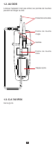
1. PRÉSENTATION 1.1. C.A 742 Cordon noir terminé par une pointe de touche. Pointe de touche rouge. Bornes de raccordement. Bargraphe. + Indicateur de phase. COM 600V CAT IV 230 127 50 24 690 AC 400 750 DC Ph Ω + AC ELV VDC 12 Indicateur de tension dangereuse. - Indicateur de polarité. C.A 742 SAFETY TESTER AUTO TEST Ω DDT-VAT Bouton d’auto test. Dragonne détachable. Bouton de continuité.
1.2. AU DOS Lorsque l’appareil n’est pas utilisé, les pointes de touches peuvent se ranger au dos. Protection amovible. Pointe de touche rouge. Gardes. Pointe de touche noire. Trappe à pile. 1.3. C.A 742 IP2X Voir le § 2.6.
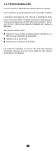
1.4. FONCTIONNALITÉS Le C.A 742 est un Détecteur De Tension (DDT) à voyants. Il est conforme aux prescriptions de la norme IEC 61243-3. La fonction principale du C.A 742 est la Vérification d’Absence de Tension (VAT). Il détecte les tensions dangereuses, c’est à dire supérieure à la TBT (très basse tension : 50 Vac ou 120 Vdc), même si les piles de l’appareil sont usées ou absentes.
2. UTILISATION Cet appareil est un détecteur. Les indications qu’il fournit ne doivent pas être utilisées à des fins de mesure. 2.1. AUTO TEST Avant d’utiliser le C.A 742, procédez à un auto test. Il permet de vérifier l’intégrité des cordons, le bon fonctionnement du circuit électronique et un niveau de tension suffisant pour les piles. Connectez la pointe de touche rouge sur la borne + et le cordon noir sur la borne COM. Amenez les 2 pointes de touche en contact et appuyez sur le bouton AUTO TEST.
Si un voyant sur trois s’éteint, c’est qu’il y a un problème au niveau des cordons. Vérifiez qu’ils sont correctement branchés et qu’ils sont bien en contact et appuyez à nouveau sur le bouton AUTO TEST. Si le problème persiste, le cordon et/ou la pointe de touche doivent être remplacés. + COM 600V CAT IV 400 230 127 50 24 12 Ω + AC VDC 690 AC 750 DC Ph ELV - Si aucun voyant n’est allumé, remplacez les piles (voir § 4.2).
Si la tension présente est : alternative : les voyants s’allument pour indiquer sa valeur et les voyants + (vert) et - (orange) sont allumés. + COM 600V CAT IV 400 230 127 50 24 12 Ω VACDC + 690 AC 750 DC Ph ELV - continue : les voyants s’allument pour indiquer sa valeur et le voyant + (vert) ou le voyant - (orange) s‘allume pour indiquer la polarité.
2.3. DÉTECTION DE CONTINUITÉ Connectez la pointe de touche rouge sur la borne + et le cordon noir sur la borne COM. Placez vos mains derrière la garde de l’appareil et de la pointe de touche. Si l’appareil n’a pas été utilisé depuis plus de 10 minutes ou s’il a été placé en veille, effectuez d’abord un auto test afin de le placer en veille active. Placez les pointes de touche sur l’élément à tester et maintenez fermement le contact. R Maintenez le bouton Ω appuyé.
Placez vos mains derrière la garde de l’appareil. AUTO TEST Ω Placez la pointe de touche sur l’élément à tester et maintenez fermement le contact. Si la pointe de touche est bien sur la phase, le voyant Ph (phase) clignote et l’appareil émet des bips sonores. + COM 600V CAT IV 400 230 127 50 24 12 Ω + AC 690 AC 750 DC Ph ELV VDC - Attention : ce n’est pas parce que le voyant Ph ne clignote pas qu’il n’y a pas de tension dangereuse sur la prise. 2.5. UTILISATION DU C.
Clipsez la pointe de touche rouge au dos de l’appareil et tenez la pointe de touche noire à la main. Pointe de touche noire. Pointe de touche rouge. Gâchettes. Zones d’appui pour déverrouillage de la protection.
Pour effectuer un test, appuyez sur la gâchette. Cela déverrouille la protection de la pointe qui peut coulisser. Vous pouvez ensuite l’introduire dans une prise ou l’amener au contact de l’objet à tester. Pour utiliser l’appareil, tenez-le dans la main, tout en appuyant avec l’index sur la gâchette de la pointe de touche rouge. Tenez la pointe de touche noire dans l’autre main tout en appuyant avec le pouce sur la gâchette.
3. CARACTÉRISTIQUES 3.1. CONDITIONS DE RÉFÉRENCE Grandeur d’influence Valeurs de référence Température 23 ± 5 °C Humidité relative 30 à 75 % HR Tension d’alimentation 3 ± 0,1 V Fréquence du signal mesuré Type de signal DC ou 45 à 65 Hz sinusoïdal Champ électrique extérieur < 1 V/m Champ magnétique DC extérieur < 40 A/m 3.2. CARACTÉRISTIQUES ÉLECTRIQUES 3.2.1. TENSION Tensions nominales : 12, 24, 50, 127, 230, 400, 690 Vac / Vdc et 750 Vdc. Fréquence de fonctionnement : DC et 16,67 à 800 Hz.
3.3. CONDITIONS D’ENVIRONNEMENT L’appareil est de type N. Il doit être utilisé dans les conditions suivantes : %HR 100 90 80 70 60 50 3 1 2 40 30 20 10 0 -50 -40 -30 -20 -10 0 °C 10 20 30 40 50 60 70 80 90 1 : Domaine de référence 2 : Domaine de fonctionnement -15 à +45 °C et 20 à 95 % HR hors condensation. (35°C max à 95%HR) 3 : Domaine de stockage (sans pile) -40 à +70 °C et 20 à 95 % HR hors condensation. En cas de non utilisation prolongée ou de stockage, retirer les piles du boîtier.
3.6. CONFORMITÉ AUX NORMES INTERNATIONALES Détecteur de tension bipolaire IEC 61243-3 Ed. 2 de 2010. Conforme aux prescriptions de la NFC 18-510. L’appareil est conforme selon l’IEC 61010-1, 600V CAT IV. 3.7. COMPATIBILITÉ ÉLECTROMAGNÉTIQUE Émission et immunité en milieu industriel selon IEC 61326-1.
4. MAINTENANCE Excepté les piles, l’appareil ne comporte aucune pièce susceptible d’être remplacée par un personnel non formé et non agréé. Toute intervention non agréée ou tout remplacement de pièce par des équivalences risque de compromettre gravement la sécurité. 4.1. NETTOYAGE L’appareil doit être maintenu en parfait état de propreté. Déconnectez tout branchement de l’appareil. Utilisez un chiffon doux, légèrement imbibé d’eau savonneuse.
ou votre centre technique régional Manumesure qui établira un dossier de retour et vous communiquera la procédure à suivre. Coordonnées disponibles sur notre site : http://www.chauvin-arnoux.com ou par téléphone aux numéros suivants : 02 31 64 51 55 (centre technique Manumesure), 01 44 85 44 85 (Chauvin Arnoux). Pour les réparations hors de France métropolitaine, sous garantie et hors garantie, retournez l’appareil à votre agence Chauvin Arnoux locale ou à votre distributeur. 5.
6. POUR COMMANDER Détecteur de tension C.A 742 .......................P01191742Z Livré sous blister avec : une pointe de touche rouge Ø 2 mm, un cordon noir terminé par une pointe de touche Ø 2 mm, une dragonne, deux piles alcaline AAA ou LR3, une notice de fonctionnement 5 langues, un certificat de vérification. Détecteur de tension C.A 742 IP2X................
ENGLISH Thank you for purchasing a C.A 742 or a C.A 742 IP2X voltage detector. For best results from your instrument: read these operating instructions carefully, comply with the precautions for use. WARNING, risk of DANGER! The operator must refer to these instructions whenever this danger symbol appears. Equipment protected by double insulation. Equipment suitable for live work. Battery. Earth. The CE marking indicates conformity with European directives, in particular LVD and EMC.
PRECAUTIONS FOR USE This device is protected against voltages up to 600V with respect to earth in measurement category IV. The protection provided by the device may be compromised if it is used other than as specified by the manufacturer and so endanger the user. Do not exceed the maximum rated voltage and current and the measurement category. Do not use your instrument on networks of which the voltage or category exceeds those stated.
1. PRESENTATION 1.1. C.A 742 Black lead terminated by a test probe. Red test probe. Connection terminals. Bargraph. + 230 127 50 24 12 Phase indicator. COM 600V CAT IV 690 AC 400 750 DC Ph Ω V + AC DC ELV Hazardous voltage indicator. - C.A 742 Polarity indicator. SAFETY TESTER AUTO TEST Ω DDT-VAT Self-test button. Detachable strap. Continuity button.
1.2. ON THE BACK When the device is not in use, the test probes can be stowed on the back. Removable protective caps. Red test probe. Guards. Black test probe. Battery compartment cover. 1.3. C.A 742 IP2X See §2.6.
1.4. FUNCTIONS The C.A 742 is a Voltage Detector with indicator lights. It complies with the requirements of standard IEC 61243-3. The main function of the C.A 742 is to test for the absence of any voltage. It detects hazardous voltages, meaning voltages exceeding the ELV (extra low voltage: 50 Vac or 120 Vdc), even if its batteries are low or missing. Its other functions are: Indication of a voltage between 12 and 690 Vac or 750 Vdc, with indication of the polarity. Continuity indication.
2. USE This device is a detector. The indications it provides must not be used for measurement purposes. 2.1. SELF-TEST Before using the C.A 742, perform a self-test. This checks the integrity of the leads, the proper operation of the electronic circuit, and the battery voltage. Connect the red test probe to the + terminal and the black lead to the COM terminal. Touch the 2 test probes together and press the AUTO TEST button. Press for as long as necessary.
If every third indicator is off, there is a problem with the leads. Check that they are correctly connected and that they are actually touching, then press the AUTO TEST button again. If the problem persists, the lead and/or the test probe must be replaced. + COM 600V CAT IV 400 230 127 50 24 12 Ω VACDC + 690 AC 750 DC Ph ELV - If no indicator lights, replace the batteries (see §4.2). If the problem persists with new batteries, the device is defective and must be sent in for repair (see §4.
If the voltage present is: AC, the indicators light to indicate its value and the + (green) and - (orange) indicators light. + COM 600V CAT IV 400 230 127 50 24 12 Ω VACDC + 690 AC 750 DC Ph ELV - DC, the indicators light to indicate its value and the + indicator (green) or the - indicator (orange) lights to indicate the polarity.
2.3. CONTINUITY DETECTION Connect the red test probe to the + terminal and the black lead to the COM terminal. Keep your hands behind the guards of the device and of the test probe. If the device has been left unused for more than 10 minutes or has been set to standby, first perform a SELF-TEST in order to switch it to hot standby. Place the test probes on the element to be tested and maintain a firm contact. R Keep the Ω button pressed. If no voltage is detected, the C.
Ω AUTO TEST If the test probe is in fact on the phase, the Ph (phase) indicator flashes and the device beeps. + COM 600V CAT IV 400 230 127 50 24 12 Ω VACDC + 690 AC 750 DC Ph ELV - Warning: if the Ph indicator is not flashing, that does not mean that there is no hazardous voltage on the outlet. 2.5. USING THE C.A 751 (OPTION) If you have purchased a C.A 751 2P+T adapter, you can test for the absence of voltage between the phase and neutral on an outlet. Attention: Pairing the C.
Clip the red probe tip to the back of the device and hold the black probe tip in your hand. Black probe tip. Red probe tip. Triggers. Where to press to unlock the protection.
To perform a test, press the trigger. That unlocks the protection of the probe tip, which can slide. You can then insert it in an outlet or touch the object to be tested with it. To use the device, hold it in your hand while pressing the trigger of the red probe tip with your index finger. Hold the black probe tip in your other hand while pressing the trigger with your thumb.
3. CHARACTERISTICS 3.1. REFERENCE CONDITIONS Quantity of influence Reference values Temperature 23±5°C Relative humidity 30 to 75 % HR Supply voltage 3±0,1V Frequency of the measured signal Type of signal DC or 45 to 65 Hz sinusoidal External electric field <1V/m DC external magnetic field <40A/m 3.2. ELECTRICAL CHARACTERISTICS 3.2.1. VOLTAGE Nominal voltages: 12, 24, 50, 127, 230, 400, 690 Vac/Vdc and 750 Vdc. Frequency of operation: DC and 16.67 at 800Hz. Maximum input current: 3.5 mArms.
3.3. ENVIRONMENTAL CONDITIONS The device is of type N. It must be used under the following conditions: %RH 100 90 80 70 60 50 3 1 2 40 30 20 10 0 -50 -40 -30 -20 -10 0 °C 10 20 30 40 50 60 70 80 90 1: Reference domain 2: Operating range -15 to +45°C and 20 to 95% RH without condensation. (35°C max. at 95% RH) 3: Range in storage (without batteries) -40 to +70°C and 20 to 95% RH without condensation.
3.6. COMPLIANCE WITH INTERNATIONAL STANDARDS Two-pole voltage detector per IEC 61243-3 ed. 2 of 2010. The device is in conformity with IEC-61010-1 600V, CAT IV. 3.7. ELECTROMAGNETIC COMPATIBILITY Emissions and immunity in an industrial setting compliant with IEC 61326-1.
4. MAINTENANCE Except for the batteries, the instrument contains no parts that can be replaced by personnel who have not been specially trained and accredited. Any unauthorized repair or replacement of a part by an “equivalent” may gravely impair safety. 4.1. CLEANING The device must be kept perfectly clean. Disconnect the instrument completely. Use a soft cloth, dampened with soapy water. Rinse with a damp cloth and dry rapidly with a dry cloth or forced air. Do not use alcohol, solvents, or hydrocarbons.
5. WARRANTY Except as otherwise stated, our warranty is valid for twelve months starting from the date on which the equipment was sold. Extract from our General Conditions of Sale provided on request.
6. TO ORDER C.A 742 voltage detector ...............................P01191742Z Delivered in blister pack with: one red test probe 2mm in diameter, one black lead terminated by a test probe 2mm in diameter, one strap, two AAA or LR3 alkaline batteries, one user’s manual in 5 languages, one verification certificate. C.A 742 IP2X voltage detector.......................
DEUTSCH Sie haben einen Spannungsprüfer C.A 742 oder C.A 742 IP2X erworben und wir danken Ihnen für Ihr Vertrauen. Um die optimale Benutzung Ihres Gerätes zu gewährleisten, bitten wir Sie: diese Bedienungsanleitung sorgfältig zu lesen die Benutzungshinweise genau zu beachten. A C H T U N G , G E FA H R ! S o b a l d d i e s e s Gefahrenzeichen irgendwo erscheint, ist der Benutzer verpflichtet, die Anleitung zu Rate zu ziehen. Das Gerät ist durch eine doppelte Isolierung geschützt.
SICHERHEITSHINWEISE Geräteschutz für max. Spannung von 600V gegenüber Erde bei Anlagen der Messkategorie IV. Der Geräteschutz und damit eine gefahrlose Handhabung sind nur dann gegeben, wenn das Gerät nach Herstellerangaben verwendet wird. Halten Sie sich an die Messkategorie und die max. zul. Nennspannungen und -ströme.
1. VORSTELLUNG 1.1. C.A 742 Fest angeschlossenes Kabel (schwarz) an Tastspitze Rote Tastspitze Anschlussbuchsen Balkenanzeige + 230 127 50 24 12 Phasenan zeige COM 600V CAT IV 690 AC 400 750 DC Ph Ω + AC ELV VDC Anzeige bei Gefahren spannung - Polaritäts anzeige C.
1.2. RÜCKSEITE Die Tastspitzen finden an der Rückseite Platz, wenn das Gerät nicht im Einsatz ist. Stöpsel Rote Tastspitze Fingerschutz Schwarze Tastspitze Batteriefach. 1.3. C.A 742 IP2X Siehe Kapitel 2.6.
1.4. FUNKTIONSUMFANG C.A 742 ist ein Spannungsprüfer mit LEDs. Entspricht der IEC 61243-3-Norm. Die Hauptfunktion des C.A 742 ist die Überprüfung der Spannungsfreiheit. Das Gerät erkennt auch bei fehlender oder schwacher Batterie eine Gefahrenspannung, das heißt alle die Schutzkleinspannung (ELV: 50 Vac bzw. 120 Vdc) übersteigenden Spannungen. Sonstige Gerätefunktionen: Spannungsprüfung von 12 bis 690 Vac bzw. 750 Vdc mit Polaritätsanzeige Durchgängigkeitsqualität Phasenanzeige Der C.
2. VERWENDUNG Es handelt sich um ein Prüfgerät, das nicht für Messeinsätze geeignet ist. 2.1. SELBSTTEST Führen Sie einen Selbsttest durch, bevor Sie den C.A 742 verwenden. Der Geräte-Selbsttest überprüft, dass die Kabel unbeschädigt sind, dass der Schaltkreis einwandfrei funktioniert und dass die Batterien nicht zu schwach sind. Stecken Sie dazu die rote Tastspitze in die +-Buchse und die schwarze Leitung in den COM-Anschluss.
Eine von drei LEDs leuchtet nicht: Die Leitungen sind nicht einwandfrei. Sie müssen überprüfen, ob die Leitungen ordentlich angeschlossen sind und Kontakt haben. Dann den AUTO TEST wiederholen. Wenn das Problem damit nicht behoben ist, müssen Sie die Leitung und/oder die Tastspitze austauschen. + COM 600V CAT IV 400 230 127 50 24 12 Ω + AC 690 AC 750 DC Ph ELV VDC - Keine einzige LED leuchtet: Die Batterien müssen ausgetauscht werden (siehe Abs. 4.2.).
Spannung vorhanden mit folgender Anzeige: Wechselspannung: Die LEDs zeigen den Wert an und die LEDs + (grün) und- (orange) leuchten. + COM 600V CAT IV 400 230 127 50 24 12 Ω VACDC + 690 AC 750 DC Ph ELV - Gleichspannung: Die LEDs zeigen den Wert an und die LED + (grün) oder die LED- (orange) leuchtet und zeigt damit die Polarität an. + COM 600V CAT IV 127 50 24 750 DC Ω VACDC 12 690 AC 400 230 + Ph ELV - Gefahrenspannung, d.h. >50 Vac bzw.
2.3. DURCHGANGSPRÜFUNG Stecken Sie dazu die rote Tastspitze in die +-Buchse und die schwarze Leitung in den COM-Anschluss. Fassen Sie das Gerät immer hinter dem Fingerschutz an Gerät und Tastspitze an. Wenn Sie das Gerät seit mehr als 10 Minuten nicht mehr verwendet haben bzw. wenn es auf Standby war, führen Sie zuerst einen SELBSTTEST durch. Damit wird das Gerät wieder „aufgeweckt“. Halten Sie die Tastspitzen fest an den Prüfling. R Halten Sie dann die Taste Ω gedrückt. C.
Ω AUTO TEST Wenn die Tastspitze an der Phase liegt, blinkt die LED Ph (Phase). Außerdem erklingt ein akustisches BEEP-Signal. + COM 600V CAT IV 400 230 127 50 24 12 Ω VACDC + 690 AC 750 DC Ph ELV - Achtung: Gefahrenspannung am Stecker kann auch dann vorhanden sein, wenn die LED Ph nicht blinkt! 2.5. BEDIENUNG C.A 751 (OPTION) Mit dem Zubehör 2P+N-Adapter bietet der C.A 751 die Möglichkeit, einen Stecker zwischen Phase und Neutralleiter auf Spannungsfreiheit zu prüfen. Achtung: Wenn Sie den C.
Klemmen Sie die rote Tastspitze hinten am Gerät an und nehmen Sie die schwarze Tastspitze in die Hand. Schwarze Tastspitze. Rote Tastspitze. Auslöser. Druckfläche zum Entriegeln der Schutzvorkehrung.
Die Auslöser drücken, um einen Test v o r z u n e h m e n . D a d u rc h w i rd d i e Schutzvorkehrung an der Spitze entriegelt, diese kann nun verschoben werden. Nun kann sie in eine Buchse eingeführt bzw. mit dem Testobjekt in Kontakt gebracht werden. Nehmen Sie das Gerät in die Hand und drücken Sie gleichzeitig mit dem Zeigefinger auf den Auslöser der roten Tastspitze. Halten Sie die schwarze Tastspitze in der anderen Hand und drücken Sie gleichzeitig mit dem Daumen auf den Auslöser.
3. TECHNISCHE DATEN 3.1. REFERENZBEDINGUNGEN Einflussgröße Bezugswerte Temperatur 23±5 °C Relative Luftfeuchte 30 bis 75% r.F. Versorgungsspannung 3±0,1 V Signalfrequenz des Messsignals Signalform DC oder 45 bis 65 Hz Sinus Elektrische Feldstärke <1 V/m Magnetfeldstärke DC <40 A/m 3.2. ELEKTRISCHE DATEN 3.2.1 SPANNUNG Nennspannungen: 12, 24, 50, 127, 230, 400, 690 Vac/Vdc und 750 Vdc. Betriebsbereich: DC od. 16,67 … 800Hz Max. Eingangssignalstärke: 3,5 mArms Eingangsimpedanz >300kΩ.
3.3. UMGEBUNGSBEDINGUNGEN Es handelt sich um ein Gerät der Type N, folgende Einsatzbedingungen sind zu berücksichtigen: % r.F. 100 90 80 70 60 3 50 1 2 40 30 20 10 0 -50 -40 -30 -20 -10 0 °C 10 20 30 40 50 60 70 80 90 1: Referenzbereich 2: Funktionsbereich -15 bis +45°C und 20 bis 95% r.F. ohne Kondenswasser. (max. 35°C bei 100% r.F. ) 3: Lagerbereich (ohne Batterie) -40 bis +70°C und 20 bis 95% r.F. ohne Kondenswasser.
3.6. KONFORMITÄT MIT INTERNATIONALEN NORMEN Zweipoliger Spannungsprüfer IEC 61243-3 Ausg. 2 aus dem Jahr 2010. Der Gerät entspricht IEC 61010-1, 600 V CAT IV. 3.7. ELEKTROMAGNETISCHE VERTRÄGLICHKEIT Störaussendung und Störimmunität im industriellen Umfeld gemäß IEC 61326-1.
4. WARTUNG Außer den Batterien enthält das Gerät keine Teile, die von nicht ausgebildetem oder nicht zugelassenem Personal ausgewechselt werden dürfen. Jeder unzulässige Eingriff oder Austausch von Teilen durch sog. „gleichwertige“ Teile kann die Gerätesicherheit schwerstens gefährden. 4.1. REINIGUNG Halten Sie das Gerät immer tadellos sauber. Das Gerät von jeder Verbindung trennen. Das Gerät mit einem leicht mit Seifenwasser angefeuchteten Tuch reinigen.
5. GARANTIE Unsere Garantie erstreckt sich, soweit nichts anderes ausdrücklich gesagt ist, auf eine Dauer von zwölf Monaten nach Überlassung des Geräts (Auszug aus unseren allgemeinen Geschäftsbedingungen, die Sie gerne anfordern können). Eine Garantieleistung ist in folgenden Fällen ausgeschlossen: Bei unsachgemäßer Benutzung des Geräts oder Benutzung in Verbindung mit einem inkompatiblen anderen Gerät. Nach Änderungen am Gerät, die ohne ausdrückliche Genehmigung des Herstellers vorgenommen wurden.
6. BESTELLANGABEN Spannungsprüfer C.A 742 ..............................P01191742Z Lieferung in Blisterverpackung mit 1 rote Prüfspitze Ø2mm 1 fest angeschlossenes Kabel (schwarz) an Tastspitze Ø2mm 1 Trageschlaufe 2 Alkalibatterien, AAA bzw. LR3, 1 Bedienungsanleitung in 5 Sprachen, 1 Prüfzertifikat. Spannungsprüfer C.A 742 IP2X......................
ITALIANO Avete appena acquistato un rivelatore di tensione C.A 742 o C.A 742 IP2X. Vi ringraziamo per la fiducia che ci avete accordato. Per ottenere le migliori prestazioni dal vostro strumento: Leggete attentamente il presente manuale d’uso. Rispettate le precauzioni d’uso. ATTENZIONE, rischio di PERICOLO! L’operatore deve consultare il presente manuale d’uso ogni volta che vedrà questo simbolo di pericolo. Strumento protetto da doppio isolamento. Materiale indicato per i lavori sotto tensione.
PRECAUZIONI D’USO Questo strumento è protetto contro le tensioni non superiori a 600V rispetto alla terra nella categoria di misura IV. Se si utilizza lo strumento in maniera non conforme alle specifiche del costruttore, la sua protezione non potrà più essere garantita e l’utente sarà allora in pericolo. Rispettate la tensione massima assegnata e la categoria di misura. Non utilizzare lo strumento su reti con tensione (o categoria) superiore a quelle indicate.
1. PRESENTAZIONE 1.1. C.A 742 Cavo nero con una punta di contatto all’estremità. Punta di contatto rossa. Morsetti di raccordo. Bargraph. + 230 127 50 24 12 Indicatore di fase. COM 600V CAT IV 690 AC 400 750 DC Ph Ω + AC ELV VDC Indicatore di tensione pericolosa. - Indicatore di polarità. C.A 742 SAFETY TESTER AUTO TEST Ω DDT-VAT Bottone d’auto-test. Bottone di continuità. 58 Cinghia amovibile.
1.2. SUL RETRO Quando lo strumento non è utilizzato, le punte di contatto possono sistemarsi sul retro. Protezioni amovibili. Punta di contatto rossa. Guardie. Punta di contatto nera. Vano della pila. 1.3. C.A 742 IP2X Consultare § 2.6.
1.4. FUNZIONALITÀ Il C.A 742 è un Rivelatore Di Tensione (RDT) dotato di spie. Strumento conforme alle prescrizioni della norma EN 61243-3. La funzione principale del C.A 742 è la Verifica d’Assenza di Tensione (VAT). Esso rivela le tensioni pericolose, ossia superiori alla TMB (tensione molto bassa: 50 Vac o 120 Vdc), anche se le pile dello strumento sono scariche o assenti. Le sue altre funzioni sono: Indicazione di una tensione compresa fra 12 e 690 Vac oppure 750 Vdc con indicazione della polarità.
2. UTILIZZO Questo strumento è un rivelatore: le indicazioni che fornisce non vanno utilizzate a fini di misura. 2.1. AUTO-TEST Prima di utilizzare il C.A 742, procedete ad un auto test che permette di verificare l’integrità dei cavi, il corretto funzionamento del circuito elettronico e un livello di tensione sufficiente per le pile. Collegate la punta di contatto rossa al morsetto + e il cavo nero al morsetto COM. Avvicinate le 2 punte di contatto (devono toccarsi) e premete il bottone AUTO TEST.
Se una spia su tre si spegne, ciò significa che c’è un problema a livello dei cavi. Verificate che siano correttamente allacciati e bene in contatto dopodiché premete di nuovo il bottone AUTO TEST. Se il problema persiste, il cavo e/o la punta di contatto vanno sostituiti. + COM 600V CAT IV 400 230 127 50 24 12 Ω VACDC + 690 AC 750 DC Ph ELV - Se nessuna spia è accesa, sostituite le pile (consultare §4.2).
Se la tensione presente è: alternata: le spie si accendono per indicare il suo valore e le spie + (verde) e - (arancione) sono accese. + COM 600V CAT IV 400 230 127 50 24 12 Ω VACDC + 690 AC 750 DC Ph ELV - continua: le spie si accendono per indicare il suo valore e la spia + (verde) o la spia - (arancione) si accende per indicare la polarità.
2.3. RIVELAZIONE DI CONTINUITÀ Collegate la punta di contatto rossa al morsetto + e il cavo nero al morsetto COM. Mettete le mani dietro la guardia dello strumento e della punta di contatto. Se lo strumento non è stato utilizzato da più di 10 minuti o se è stato messo in standby, effettuate dapprima un AUTOTEST per metterlo in standby attivo. Posizionate le punte di contatto sull’elemento da testare e mantenete fermamente il contatto. R Mantenete premuto il bottone Ω .
AUTO TEST Ω Posizionate le punte di contatto sull’elemento da testare e mantenete fermamente il contatto. Se la punta di contatto è correttamente sulla fase, la spia Ph (fase) lampeggia e lo strumento emette vari bip sonori. + COM 600V CAT IV 400 230 127 50 24 12 Ω + AC 690 AC 750 DC Ph ELV VDC - Attenzione: anche se la spia Ph non lampeggia, sulla presa può trovarsi una tensione pericolosa. 2.5. UTILIZZO DEL C.A 751 (OPZIONE) Se avete acquistato un adattatore 2P+T, C.
Clipsate la punta di contatto rossa sul retro dello strumento e tenete in mano la punta di contatto nera. Punta di contatto nera. Punta di contatto rossa. Grilletti. Zone d’appoggio per sbloccare la protezione.
Per effettuare un test, premete il grilletto: sbloccherete così la protezione della punta che può scorrere. Potete in seguito introdurla in una presa o metterla in contatto con l’oggetto da testare. Per utilizzare lo strumento, tenetelo in mano, premendo sempre con l’indice il grilletto della punta di contatto rossa. Tenete la punta di contatto nera nell’altra mano premendo sempre con il pollice il grilletto.
3. CARATTERISTICHE 3.1. CONDIZIONI DI RIFERIMENTO Grandezza d’influenza Valori di riferimento Temperatura 23 ± 5 °C Umidità relativa 30 a 75 % UR Tensione d’alimentazione 3 ± 0,1 V Frequenza del segnale misurato Tipo di segnale DC o 45 a 65 Hz sinusoidale Campo elettrico esterno < 1 V/m Campo magnetico DC esterno < 40 A/m 3.2. CARATTERISTICHE ELETTRICHE 3.2.1. TENSIONE Tensioni nominali: 12, 24, 50, 127, 230, 400, 690 Vac/Vdc e 750 Vdc. Frequenza di funzionamento: DC e 16,67 a 800Hz.
3.3. CONDIZIONI AMBIENTALI Lo strumento è di tipo N. Il, va quindi utilizzato nelle seguenti condizioni: % UR 100 90 80 70 60 50 3 1 2 40 30 20 10 0 -50 -40 -30 -20 -10 0 °C 10 20 30 40 50 60 70 80 90 1: Campo di riferimento 2: Campo di funzionamento -15 a +45°C e 20 al 95% UR fuori condensazione. (35°C maxi al 95%UR) 3: Campo di stoccaggio (senza batteria) -40 a +70°C t 20 al 95% UR fuori condensazione. In caso di prolungato inutilizzo o di stoccaggio, rimuovere le pile dallo strumento.
3.6. CONFORMITÀ ALLE NORME INTERNAZIONALI Rivelatore di tensione bipolare IEC 61243-3 ed. 2 (anno: 2010) Lo strumento è conforme alla norma IEC 61010-1, 600V CAT IV. 3.7. COMPATIBILITÀ ELETTROMAGNETICA Emissione e immunità in ambiente industriale secondo EN 61326-1.
4. MANUTENZIONE Tranne le pile, lo strumento non comporta pezzi sostituibili da personale non formato e non autorizzato. Qualsiasi intervento non autorizzato o qualsiasi sostituzione di pezzi con pezzi equivalenti rischia di compromettere gravemente la sicurezza. 4.1. PULIZIA Lo strumento deve essere mantenuto in perfetto stato di pulizia. Disinserire completamente lo strumento. Utilizzare un panno soffice, leggermente inumidito con acqua saponata.
5. GARANZIA Salvo stipulazione espressa la nostra garanzia si esercita, dodici mesi a decorrere dalla data di messa a disposizione del materiale. L’estratto delle nostre Condizioni Generali di Vendita sarà comunicato su domanda.
6. PER ORDINARE Rivelatore di tensione C.A 742 ......................P01191742Z Fornito sotto blister con: una punta di contatto rossa Ø2mm, un cavo nero con una punta di contatto (Ø2mm) all’estremità, una cinghia, due pile alcaline AAA oppure LR3, un manuale d’uso in 5 lingue, un certificato di verifica. Rivelatore di tensione C.A 742 IP2X..............
ESPAÑOL Usted acaba de adquirir un detector de tensión C.A 742 o C.A 742 IP2X y le agradecemos la confianza que ha depositado en nosotros. Para conseguir las mejores prestaciones de su instrumento: lea atentamente este manual de instrucciones, respete las precauciones de uso. ¡ATENCIÓN, riesgo de PELIGRO! El operador debe consultar el presente manual de instrucciones cada vez que aparece este símbolo de peligro. Instrumento protegido mediante doble aislamiento.
PRECAUCIONES DE USO Este instrumento está protegido contra tensiones que no superan 600 V con respecto a la tierra en la categoría de medida IV. La protección garantizada por el instrumento puede verse alterada si el mismo se utiliza de forma no especificada por el fabricante y poner así en peligro al usuario. Respete la tensión y la intensidad máximas asignadas así como la categoría de medida. No utilice el instrumento en redes cuya tensión o categoría sea superior a las mencionadas.
1. PRESENTACIÓN 1.1. C.A 742 Cable negro acabado por una punta de prueba. Punta de prueba roja. Bornes de conexión. Barra analógica. + 230 127 50 24 12 Indicador de fase. COM 600V CAT IV 690 AC 400 750 DC Ph Ω V + AC DC ELV Indicador de tensión peligrosa. - C.A 742 Indicador de polaridad. SAFETY TESTER AUTO TEST Ω DDT-VAT Botón de AUTO-TEST. Correa separable. Botón de continuidad.
1.2. EN EL DORSO Cuando no se utiliza el instrumento, las puntas de prueba pueden guardarse en el dorso. Protecciones amovibles. Punta de prueba roja. Protecciones. Punta de prueba negra. Tapa de las pilas. 1.3. C.A 742 IP2X Véase §2.6.
1.4. FUNCIONES El C.A 742 es un Detector De Tensión (DDT) con pilotos. Cumple con los requisitos de la norma IEC 61243-3. La función principal del C.A 742 es la verificación de ausencia de tensión (VAT). Detecta las tensiones peligrosas, es decir superior a la MBT (muy baja tensión: 50 Vac o 120 Vdc), aunque las pilas del instrumento estén gastadas o ausentes. Sus demás funciones son: Indicación de una tensión comprendida entre 12 y 690 Vac o 750 Vdc con indicación de la polaridad.
2. UTILIZACIÓN Este instrumento es un detector. Las indicaciones que proporciona no deben utilizarse para realizar medidas. 2.1. AUTO-TEST Antes de utilizar el C.A 742, efectúe un auto-test. Permite verificar el buen estado de los cables, el correcto funcionamiento del circuito electrónico y un nivel de tensión suficiente para las pilas. Conecte la punta de prueba roja al borne + y el cable negro al borne COM. Haga que las 2 puntas de prueba entren en contacto y presione el botón AUTO TEST.
Si se apaga un piloto de cada tres, es que hay un problema con los cables. Compruebe que estén correctamente conectados y que estén en contacto y presione de nuevo el botón AUTO TEST. Si el problema persiste, se debe cambiar el cable y/o la punta de prueba. + COM 600V CAT IV 400 230 127 50 24 12 Ω VACDC + 690 AC 750 DC Ph ELV - Si no se enciende ningún piloto, cambie las pilas (véase §4.2).
Si la tensión presente es: alterna: los pilotos se encienden para indicar su valor y los pilotos + (verde) y - (naranja) están encendidos. + COM 600V CAT IV 400 230 127 50 24 12 Ω + AC 690 AC 750 DC Ph ELV VDC - continua: los pilotos se encienden para indicar su valor y el piloto + (verde) o el piloto - (naranja) se enciende para indicar la polaridad.
2.3. DETECCIÓN DE CONTINUIDAD Conecte la punta de prueba roja en el borne + y el cable negro en el borne COM. Posicione las manos detrás de la protección del instrumento y de la punta de prueba. Si el instrumento no se ha utilizado desde hace más de 10 minutos o si está en modo en espera, realice primero un auto-test para ponerlo en modo en espera activo. Coloque las puntas de prueba sobre el elemento a probar y mantenga firmemente el contacto. R Mantenga el botón Ω pulsado.
AUTO TEST Ω Coloque la punta de prueba sobre el elemento a probar y mantenga firmemente el contacto. Si la punta de prueba está en contacto con la fase, el piloto Ph (fase) parpadea y el instrumento emite señales acústicas. + COM 600V CAT IV 400 230 127 50 24 12 Ω + AC 690 AC 750 DC Ph ELV VDC - Atención: no es porque el piloto Ph no parpadea que no hay una tensión peligrosa en la toma. 2.5. UTILIZACIÓN DEL C.A 751 (OPCIONAL) Si ha adquirido un adaptador 2P+T, C.
Enganche la punta de prueba roja al dorso del instrumento y sujete la punta de prueba negra con la mano. Punta de prueba negra. Gatillos. Zonas de apoyo para desbloquear la protección. 84 Punta de prueba roja.
Para realizar una prueba, presione el gatillo. Esto desbloquea la protección de la punta que puede deslizarse. Puede usted entonces introducirla en una toma o ponerla en contacto con el objeto a probar. Para utilizar el instrumento, sujételo en la mano, mientras presiona el gatillo de la punta de prueba roja con el dedo índice. Sujete la punta de prueba negra con la otra mano mientras presiona el gatillo con el pulgar.
3. CARACTERÍSTICAS 3.1. CONDICIONES DE REFERENCIA Magnitud de influencia Valores de referencia Temperatura 23 ± 5 °C Humedad relativa 30 a 75 % HR Tensión de alimentación 3 ± 0,1 V Frecuencia de la señal medida Tipo de señal DC o 45 a 65 Hz sinusoidal Campo eléctrico exterior < 1 V/m Campo magnético DC exterior < 40 A/m 3.2. CARACTERÍSTICAS ELÉCTRICAS 3.2.1. TENSIÓN Tensiones nominales: 12, 24, 50, 127, 230, 400, 690 Vac/ Vdc y 750 Vdc. Frecuencia de funcionamiento: DC y 16,67 a 800 Hz.
3.3. CONDICIONES AMBIENTALES El instrumento es de tipo N. Debe utilizarse en las siguientes condiciones: %HR 100 90 80 70 60 50 3 1 2 40 30 20 10 0 -50 -40 -30 -20 -10 0 °C 10 20 30 40 50 60 70 80 90 1: Rango de referencia 2: Rango de funcionamiento -15 a +45 °C y 20 a 95% HR sin condensación. (35 °C máx. a 95% HR) 3: Rango de almacenamiento (sin pila) -40 a +70 °C y 20 a 95% HR sin condensación.
3.6. CONFORMIDAD CON LAS NORMAS INTERNACIONALES Detector de tensión bipolar IEC 61243-3 Ed.2 de 2010. El instrumento es conforme según IEC 61010-1, 600 V CAT IV. 3.7. COMPATIBILIDAD ELECTROMAGNÉTICA Emisión e inmunidad en medio industrial según IEC 61326-1.
4. MANTENIMIENTO Salvo las pilas, el instrumento no contiene ninguna pieza que pueda ser sustituida por un personal no formado y no autorizado. Cualquier intervención no autorizada o cualquier pieza sustituida por piezas similares pueden poner en peligro seriamente la seguridad. 4.1. LIMPIEZA El instrumento debe conservarse perfectamente limpio. Desconecte todas las conexiones del instrumento. Utilice un paño suave ligeramente empapado con agua jabón.
5. GARANTÍA Nuestra garantía tiene validez, salvo estipulación expresa, durante doce meses a partir de la fecha de entrega del material. El extracto de nuestras Condiciones Generales de Venta, se comunica a quien lo solicite.
6. PARA PEDIDOS Detector de tensión C.A 742 .........................P01191742Z Suministrado en blíster con: una punta de prueba roja Ø2 mm, un cable negro acabado por una punta de prueba Ø2 mm, una correa, dos pilas alcalinas AAA o LR3, un manual de instrucciones en 5 idiomas, un certificado de verificación. Detector de tensión C.A 742 IP2X..................
03 - 2015 Code 694776A00 - Ed. 1 DEUTSCHLAND - Chauvin Arnoux GmbH Ohmstraße 1 - 77694 Kehl / Rhein Tel: (07851) 99 26-0 - Fax: (07851) 99 26-60 ESPAÑA - Chauvin Arnoux Ibérica S.A. C/ Roger de Flor, 293 - 1a Planta - 08025 Barcelona Tel: 90 220 22 26 - Fax: 93 459 14 43 ITALIA - Amra SpA Via Sant’Ambrogio, 23/25 - 20846 Macherio (MB) Tel: 039 245 75 45 - Fax: 039 481 561 ÖSTERREICH - Chauvin Arnoux Ges.m.b.