C.
Signification du symbole ATTENTION, risque de DANGER! L'opérateur doit consulter la présente notice à chaque fois que ce symbole de danger est rencontré. Signification du symbole Appareil entièrement protégé par isolation double ou isolation renforcée. Signification du symbole La poubelle barrée signifie que, dans l'Union Européenne, le produit fait l'objet d'une collecte sélective conformément à la directive DEEE 2002/96/EC. Vous venez d’acquérir un multimètre C.
ENGLISH ............................................................................................... 13 DEUTSCH ............................................................................................. 24 ITALIANO ............................................................................................. 35 ESPANOL .............................................................................................. 46 SOMMAIRE 1 Page - Présentation ......................................................
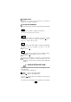
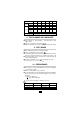
2 - DESCRIPTION (Voir dessin en § 15 - ANNEXE) 1 BORNES Bornes de sécurité Ø 4 mm ■ COM : commun, borne recevant le cordon noir ■ V Ω Hz : borne recevant le cordon rouge pour les tensions, résistances, test diodes et fréquences ■ 10 A : borne recevant le cordon rouge pour les calibres 10 A ■ µmA : borne recevant le cordon rouge pour les calibres µA, mA et 1A 2 AFFICHEUR ANALOGIQUE Le cadran comprend 3 échelles : ■ 2 échelles noires pour toutes les grandeurs (0.10 et 0.
6 COMMUTATEUR Commutateur 21 positions pour sélectionner les fonctions et calibres et la position arrêt (OFF). 7 TOUCHES DE COMMANDE NB : Ces touches de fonctions secondaires se manifestent sur l'afficheur numérique. Pour allumer et éteindre l'éclairage de l'afficheur. NB : Extinction automatique après 6 minutes. ~ Pour lire la valeur efficace et l'éventuelle composante continue ou alternative suivant le signal en présence ... ou ~ (voir en 3 - Valeur efficace vraie). MAX Pour lire la valeur maxi.
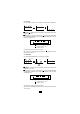
3-1 Continu Cas d'un signal continu avec composante alternative (ondulation). V V VDC + VAC V VDC VAC 0 t 0 t 0 t ■ "AUTO ..." s'affiche à la mise en marche : lecture de la composante continue seule VDC. ■ Par appuis successifs sur la touche " " : lecture du continu plus la composante alternative, de la composante alternative seule et retour au continu seul. ~ ~ ... AUTO ... ~ AUTO ... : mesure de VDC ...
4 - TENSIONS CONTINUES ET ALTERNATIVES ■ Raccorder les cordons au multimètre et se brancher en parallèle sur le circuit à contrôler. ■ Lorsque l'ordre de grandeur n'est pas connu, placer le commutateur sur le calibre le plus élevé puis baisser progressivement jusqu'au calibre approprié.
5 - DÉCIBELS ■ Rappel. La mesure d'une tension alternative peut être exprimée en décibel (symbole dB). Le décibel est le rapport de deux grandeurs ou niveau. Le niveau N, en dB d'une tension U a pour expression mathématique : N(dB) = 20 log U U 10 0 U0 est la tension de référence de 0,775 V ~ pour une puissance P0 de 1 mW sur une charge de 600 Ω. ■ Utilisation. Le niveau zéro de l'échelle rouge en dB correspond à U0=0,775 V pour le calibre 4 V ~.
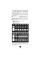
A ... 400 µA Chute de tension(1) Numérique 4 mA 40 mA 400 mV Lecture maxi 1A 1V 1,000 A 5 mA 50 mA 500 mA 1A 50 de lecture 10,00 A 1,5 % L ± 2 pt 500 µA Echelle Analogique Coefficient 10 A 650 mV 399,9 µA 3,999 mA 39,99 mA 399,9 mA Précision(2) Lecture maxi 400 mA 450 mV x 10 x 0,1 10 A 10 x1 (3) Précision x 10 x 0,1 x1 2,5 % Protection Fus. 10 A HPC Fusible 1 A HPC De 7 A à 10 A, limitation 10 min. de marche, 5 min.
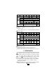
Ω Numérique Lecture maxi Précision (1) 400 Ω Ω 4 kΩ Ω 40 kΩ Ω 400 kΩ 399,9 Ω 3,999 Ω 39,99 Ω 399,9 kΩ 5 kΩ 50 kΩ (3) Lecture maxi Ω 40 MΩ (3) 1%L ± 2pt 500 Ω Echelle 500 kΩ 5 MΩ 50 MΩ x10 x0,1 x1 50 Analogique Coefficient de lecture Précision Ω 4 MΩ 3,999 MΩ 39,99 MΩ x10 x0,1 x1 (2) 2,5 % Surcharge admissible 600 V (1) En % de la lecture (L) de 10 à 100 % du calibre (2) En % de la fin d’échelle (3) 5 %L ± 5 pt 8 - TEST SONORE DE CONTINUITÉ ■ Raccordement et caractérist
- CARACTÉRISTIQUES GÉNÉRALES 11-1 Dimensions et masse ■ 56 x 105 x 160 mm ■ 500 g 11-2 Alimentation ■ Une pile 9 V (type 6F22 ou 6LF22 alcaline) ■ Autonomie : 300 heures en fonctionnement permanent 11-3 Conditions climatiques ■ Température : utilisation : 0 °C à +55 °C / stockage : -40 °C à +70 °C ■ Humidité relative : utilisation : 20 à 90 % HR / stockage : 10 à 95 % HR ■ Altitude : utilisation < 2000 m 11-4 Conformité aux normes internationales 11-4-1 Sécurité électrique (NF EN 61010-1) ■ Double isolat
14 - MAINTENANCE Pour la maintenance, utilisez seulement les pièces de rechange qui ont été spécifiées. Le fabricant ne pourra être tenu pour responsable de tout accident survenu suite à une réparation effectuée en dehors de son service après-vente ou des réparateurs agréés. 14-1 Remplacement de la pile et des fusibles Pour votre sécurité, il faut obligatoirement déconnecter les cordons du multimètre pour ouvrir la trappe à pile.
Meaning of the symbol WARNING, risk od DANGER! The operator must refer to these instructions whenever this danger symbol appears. Meaning of the symbol Equipment protected throughout by double or reinforced insulation. Meaning of the symbol The rubbish bin with a line through it indicates that, in the European Union, the product must undergo selective disposal in compliance with Directive WEEE 2002/96/EC. Thank you for purchasing a C.A 5011 Multimeter.
CONTENTS 1 Page - Presentation ....................................................... 14 2 - Description ......................................................... 15 3 - True rms value ................................................... 16 4 - DC and AC voltages (V DC and AC) ................. 18 5 - Decibels (dB) ..................................................... 19 6 - Currents (A DC and AC) ................................... 19 7 - Resistances (Ω) ......................................
2 - DESCRIPTION (See drawing in § 15 - APPENDIX) 1 TERMINALS Ø 4 mm safety terminals ■ COM : common, terminal that receives the black lead ■ V Ω Hz : terminal that receives the red lead for voltages, resistances, diode test and frequencies ■ 10 A : terminal that receives the red lead for the 10 A ranges ■ µmA : terminal that receives the red lead for the µA, mA and 1 A ranges 2 ANALOGUE DISPLAY The dial comprises 3 scales: ■ 2 black scales, for all the quantities (0.10 and 0.
6 SWITCH Switch with 21 positions to select the functions and ranges and the OFF position. 7 CONTROL KEYS NB: These secondary function keys are shown on the digital display. To switch on and off the display backlighting. NB: Auto off after 6 minutes ~ To read the rms value and the possible DC or AC component depending on the signal present, DC or AC (see in Ch.3 - RMS value) MAX To read the maximum value. MAX is displayed. Minimum acquisition time 500 ms.
3-1 DC In the case of a DC signal with AC component (ripple). V V VDC + VAC V VDC VAC 0 t 0 t 0 t ■ "AUTO ... " is displayed when the instrument is switched on: reading of the DC component only VDC. ■ By successive presses on the “ ” key: reading of DC plus the AC component, of the AC component only and return to DC only. ~ AUTO ... ~ ... ~ AUTO ... : measurement of VDC ...
4 - DC AND AC VOLTAGES ■ Connect the leads to the multimeter and connect in parallel to the circuit to be tested. ■ When the order of magnitude is not known, place the switch on the highest range then progressively lower to the appropriate range. For the 1000 V rating : Do not perform measurements < 200 V Do not perform measurements for frequencies > 500 Hz ■ Analogue reading: to get the voltage in V, multiply the value read on the appropriate scale by the reading coefficient shown in the table.
5 - DECIBELS ■ Reminder. The measurement of an AC voltage can be expressed in decibels (symbol dB). The decibel is the ratio of two quantities or levels. Level N, in dB, of a voltage U has the mathematical expression: N(dB) = 20 log10 (U U0 ) U0 is the reference voltage of 0.775 V AC for a power P0 of 1 mΩ on a load of 600Ω. ■ Use. Zero level of the red scale in dB corresponds to U0 = 0.775 for the 4V AC range. The reading is direct in dB for the 5 V AC range, on analogue only, from -20 to +16dB.
A DC 400 µA Voltage drop(1) Max reading Digital 4 mA 40 mA 400 mV 1A 10 A 1.000 A 10.00 A 650 mV 399.9 µA 3.999 mA 39.99 mA 399.9 mA Accuracy(2) 1V 1.5 % rdg ± 2 counts Max reading 500 µA 5 mA Scale Analogue 400 mA 450 mV 50 mA 500 mA 1A 50 Reading coefficient x 10 10 A 10 x 0.1 x1 (3) Accuracy x 10 x 0.1 x1 2.
400 Ω Ω 4 kΩ Ω 40 kΩ Ω 400 kΩ Max reading 399.9 Ω 3.999 Ω 39.99 Ω 399.9 kΩ Accuracy (1) (3) Ω Digital Max reading 500 Ω 5 kΩ 50 kΩ 500 kΩ 5 MΩ 50 MΩ x10 x0.1 x1 50 Reading coefficient Accuracy Ω 40 MΩ (3) 1% rdg ± 2 counts Scale Analogue Ω 4 MΩ 3.999 MΩ 39.99 MΩ x10 x0.1 x1 (2) 2.
11 - GENERALES SPECIFICATIONS 11-1 Dimensions and weight ■ 56 x 105 x 160 mm ■ 500 g 11-2 Power supply ■ One battery 9 V (type 6F22 or 6LF22 alkaline) ■ Battery life: 300 hours on permanent use 11-3 Environmental conditions ■ Temperature: use: 0 °C to +55 °C / storage: -40 °C to +70 °C ■ Relative humidity: use: 20 to 90 % RH / storage: 10 to 95 % RH ■ Altitude: use < 2000 m 11-4 Conformity with international standards 11-4-1 Electrical safety (NF EN 61010-1) ■ Double insulation: ■ Degree of pollution: 2 ■ I
14 - MAINTENANCE For maintenance, use only specified spare parts. The manufacturer will not be held responsible for any accident occurring following a repair done other than by its After Sales Service or approved repairers. 14-1 Replacing the battery and the fuses For your safety the leads must be disconnected from the multimeter before the battery cover is opened. ■ To open the cover, turn the screw 1/4 turn, anti-clockwise, using a coin or a screwdriver.
Bedeutung des Zeichens ACHTUNG, Gefahrenrisiko! Sobald dieses Gefahrenzeichen erscheint, ist der Bediener verpflichtet, die Anleitung zu Rate zu ziehen. Bedeutung des Zeichens Das Gerät ist durch eine doppelte oder verstärkte Isolierung geschützt. Bedeutung des Zeichens Der durchgestrichene Mülleimer bedeutet, dass das Produkt in der europäischen Union gemäß der Richtlinie WEEE 2002/96/EC einer Abfalltrennung unterzogen werden muss. Sie haben ein Multimeter C.
INHALTSVERZEICHNIS Seite 1 - Gerätevorstellung .............................................. 25 2 - Gerätebeschreibung .......................................... 26 3 - Echt-Effektivwert einer Größe (TRMS) ............. 27 4 - Gleich- und Wechselspannungen (V ... und ~) . 29 5 - Dezibel (dB) ....................................................... 30 6 - Gleich- und Wechselströme (A ... und ~) .......... 30 7 - Widerstandsmessung (Ω) .................................
2 - GERÄTEBESCHREIBUNG (siehe Abb. in Abschn. 15. Anhang) 1 ANSCHLUSSBUCHSEN Ø 4 mm Sicherheitsbuchsen ■ COM : COMMON bzw.
6 FUNKTIONSDREHSCHALTER Drehschalter mit 21 Stellungen zur Auswahl der Meßfunktion und des Meßbereichs, sowie zum Ausschalten des Geräts (OFF). 7 FUNKTIONSTASTEN Hinweis: Diese Tasten betreffen nur Funktionen der Digitalanzeige. Dient zum Ein- bzw. Ausschalten der Anzeigebeleuchtung Hinweis: Die Beleuchtung schaltet sich automatisch nach ca. 6 Minuten ab. ~ Dient zum Ablesen des Effektivwertes und des eventuell vorhandenen Gleich- oder Wechselstromanteils im anliegenden ...
3-1 DC-Signale Fall eines DC-Signals mit überlagertem AC-Signal (Welligkeit) V V VDC + VAC V VDC VAC 0 t 0 t 0 t ■ "AUTO ... " erscheint beim Einschalten. Das Gerät mißt und zeigt nur den DC-Anteil an. ■ Durch wiederholtes Drücken der Taste " " : werden nacheinander angezeigt: DC- + AC-Anteil, nur AC-Anteil, und wieder nur DC-Anteil. ~ AUTO ... ~ ... ~ AUTO ... : Messung von VDC alleine ...
4 - GLEICH- UND WECHSELSPANNUNGEN ■ Meßleitungen in das Multimeter einstecken und zu messende Spannung parallel an der Schaltung abgreifen. ■ Wenn die Größenordnung einer Meßgröße nicht bekannt ist, den höchsten Meßbereich wählen und stufenweise herunterschalten, bis die geeignete Empfindlichkeit erreicht ist.
5 - DEZIBEL ■ Zur Erinnerung: der Meßwert einer Wechselspannung kann auch in Dezibel (dB) angegeben werden. Damit bezeichnet man das Verhältnis zwischen zwei Spannungen bzw. Pegeln. Der Pegel N einer Spannung U wird mathematisch in dB wie folgt ausgedrückt: N(dB) = 20 log10 (U U0 ) wobei U0 die Bezugsspannung von 0,775 V~ bezeichnet, die an einer Last von 600W eine Leistung P0 von 1 mΩ abgibt.
A ... 400 µA Spannungsabfall (1) Max.Meßwert Digital 4 mA 40 mA 400 mA 400 mV 450 mV 399,9 µA 3,999 mA 39,99 mA 399,9 mA Genauigkeit(2) Max.Meßwert 10 A 1,000 A 10,00 A 1V 1,5 % Anz. ± 2 Digit 500 mA 5 mA 50 mA Skala Analog 1A 650 mV 500 mA 1A 50 Skalenfaktor x 10 10 A 10 x 0,1 x1 Genauigkeit(3) x 10 x 0,1 x1 2,5 % Max.zul. Überlast Sich. 10 A Hochleistungssicherung 1 A Zwischen 7 A und 10 A Meßdauer auf 10 Min begrenzen, danach 5 Min Pause (bis max. +40 °C).
400 Ω Ω 4 kΩ Ω 40 kΩ Ω 400 kΩ Max. Mebwert 399,9 Ω 3,999 Ω 39,99 Ω 399,9 kΩ Genauigkeit(1) (3) Max. Mebwert 500 Ω 5 kΩ 50 kΩ x10 x0,1 x1 Ω Digital Analog Ω 40 MΩ 3,999 MΩ 39,99 MΩ 1 % Anz. ± 2 Digit Skala Skalenfaktor Ω 4 MΩ (3) 500 kΩ 5 MΩ 50 MΩ x10 x0,1 x1 50 2,5 % Genauigkeit (2) Mas.zul. Überlast 600 V (1) In % der Anzeige (Anz.) zwischen 10 und 100 % des Bereichs (2) In % des Skalenendwerts (3) 5% Anz.
11 - ALLGEMEINE TECHNISCHE DATEN 11-1 Abmessungen, Gewicht ■ 56 x 105 x 160 mm ■ 500 g 11-2 Stromversorgung ■ Eine 9 V-Batterie (Typ 6F22 oder 6LF22, Alkalibatterie) ■ Batteriebetrieb: ca. 300 Std. Dauerbetrieb 11-3 Klimabedingungen ■ Temperatur: Betrieb 0 ° bis +55 °C / Lagerung -40 ° bis +70 °C ■ Rel.
14 - WARTUNG, REPARATUR Verwenden Sie für Reparaturen ausschließlich die angegebenen Ersatzteile. Der Hersteller haftet einesfalls für Unfälle oder Schäden, die nach Reparaturen außerhalb seines Kundendienstnetzes oder durch nicht von ihm zugelassene Reparaturbetriebe entstanden sind. 14-1 Ersetzen der Batterie und der Sicherungen Zu Ihrer Sicherheit müssen die Meßleitungen vor Öffnen des Batteriefachs abgezogen werden.
Significato del simbolo ATTENZIONE, RISCHIO DI PERICOLO! L'operatore deve consultare il presente manuale ogni volta che vedrà questo simbolo di pericolo.. Significato del simbolo Strumento protetto da isolamento doppio o rinforzato. Significato del simbolo La pattumiera sbarrata significa che nell'Unione Europea, il prodotto è oggetto di smaltimento differenziato conformemente alla direttiva DEEE 2002/96/CE (concernente gli apparecchi elettrici e elettronici). Avete appena acquistato un multimetro C.
SOMMARIO 1 Pagina - Presentazione .................................................... 36 2 - Descrizione ........................................................ 37 3 - Vero valore efficace ......................................... 38 4 - Tensioni continue e alternate (A ... e ~) ............. 40 5 - Decibel (dB) ....................................................... 41 6 - Correnti (A ... e ~) ............................................... 41 7 - Resistenze (Ω) ............................
2 - DESCRIZIONE (Vedere disegno § 15 - ALLEGATO) 1 MORSETTI Morsetti di sicurezza Ø 4 mm ■ COM : comune, morsetto a cui si collega il cordone nero ■ V Ω Hz : morsetto a cui si collega il cordone rosso per le tensioni, resistenze, test diodi e frequenze ■ 10 A : morsetto a cui si collega il cordone rosso per portate 10 A ■ µmA : morsetto a cui si collega il cordone rosso per portate µA, mA 2 DISPLAY ANALOGICO Il quadrante comprende 3 scale: ■ 2 scale nere, per tutte le grandezze (0...10 e 0...
6 COMMUTATORE Commutatore a 21 posizioni per la selezione di funzioni e portate, oltre alla posizione di arresto (OFF). 7 TASTI DI COMANDO N.B.: Questi tasti, per le funzioni secondarie, sono abilitati sul display digitale. Per l’accensione e la regolazione della luce del display. N.B.: Spegnimento automatico dopo 6 minuti. ~ Per leggere il valore efficace e l’eventuale componente continua o alternata secondo il segnale in presenza ... o ~ (vedere punto 3 - Vero valore efficace).
3-1 Continuo Esempio di un segnale continuo con componente alternata (ondulazione). V V VVCC DC + V VCA AC V V DC CC CA VVAC 0 t 0 t 0 t ■ All’accensione, Viene visualizzato "AUTO ... " : lettura della sola componente continua VCC. ■ Premendo in successione il tasto “ ” : lettura della componente continua più quella alternata, della sola componente alternata e di nuovo della sola componente continua. ~ AUTO ... ~ ... ~ AUTO ... : misura di VCC ...
4 - TENSIONI CONTINUE E ALTERNATE ■ Collegare i cordoni al multimetro e allacciarsi in parallelo al circuito da controllare. ■ Quando non si conosce l’ordine di grandezza, posizionare il commutatore sulla portata più alta e scendere progressivamente fino a raggiungere la portata corretta.
5 - DECIBEL ■ Nota. La misura di una tensione alternata può essere espressa in decibel (simbolo dB). Il decibel è il rapporto fra due grandezze o livelli. Il livello N, in dB, di una tensione U si esprime matematicamente come segue: N(dB) = 20 log10 (U U0 ) dove U0 è la tensione di riferimento di 0,775 V ~ per una potenza P0 di 1 mΩ su un carico di 600 Ω. ■ Utilizzo. Il livello 0 della scala rossa, in dB, corrisponde a U0 = 0,775 V per portata 4 V ~.
A ... 400 µA Caduta di tensione(1) Lettura max. Digitale 4 mA 40 mA 400 mV 1A 1V 1,000 A 10,00 A 1,5 % L ± 2 pt 500 µA 5 mA Scala 50 mA 500 mA 1A 50 Analogica Coefficiente di lettura 10 A 650 mV 399,9 µA 3,999 mA 39,99 mA 399,9 mA Precisione(2) Lettura max. 400 mA 450 mV x 10 x 0.1 10 A 10 x1 Precisione x 10 x 0.1 x1 2,5 % (3) Protezione Fusibile 10 AHBC Fusibile 1 A HPC Da 7 A a 10 A, limitazione 10 min. di funzionamento, 5 min. d’arresto fino a 40 °C max.
Ω Lettura max. Digitale 400 Ω Ω 4 kΩ Ω 40 kΩ Ω 400 kΩ 399,9 Ω 3,999 Ω 39,99 Ω 399,9 kΩ Precisione (1) Lettura max.
11 - CARATTERISTICHE GENERALI 11-1 Dimensioni e peso ■ 56 x 105 x 160 mm ■ 500 g 11-2 Alimentazione ■ Una pila 9 V (tipo 6F22 o 6LF22 alcalina) ■ Autonomia: 300 ore in funzionamento continuo 11-3 Condizioni ambientali ■ Temperatura d’utilizzo: da 0°C a +55°C immagazzinamento: da -40°C a +70°C ■ Umidità relativa: utilizzo: dal 20 al 90 % UR immagazzinamento: dal 10 al 95 % UR ■ Altitudine: utilizzo < 2000 m 11-4 Conformità alle norme internazionali 11-4-1 Sicurezza elettrica (NF EN 61010-1) ■ Doppio isolamen
14 - MANUTENZIONE Per la manutenzione, utilizzare solo i pezzi di ricambio specificati. Il costruttore non potrà essere ritenuto responsabile di alcun incidente occorso a causa di una riparazione non eseguita dal proprio servizio di assistenza post-vendita o da personale autorizzato. 14-1 Sostituzione della pila e dei fusibili Per la vostra sicurezza, è indispensabile scollegare i cordoni del multimetro prima di aprire lo scomparto della pila.
Significado del símbolo ¡ATENCIÓN, riesgo de PELIGRO! El operador debe consultar el presente manual cada vez que aparece este símbolo de peligro. Significado del símbolo Instrumento totalmente protegido mediante doble aislamiento o aislamiento reforzado. Significado del símbolo El contenedor de basura tachado significa que, en la Unión Europea, el producto deberá ser objeto de una recogida selectiva de conformidad con la directiva DEEE 2002/96/CE. Acaba de adquirir un multímetro C.
INDICE Página 1 - Presentación ...................................................... 47 2 - Descripción ........................................................ 48 3 - Verdadero valor eficaz ...................................... 49 4 - Tensión continua y alterna (V ... y ~) ................. 51 5 - Decibelios (dB) ................................................... 52 6 - Intensidades (A ... y ~) ....................................... 52 7 - Resistencias (Ω) ...............................
2 - DESCRIPCION (Véase cuadro en § 15 - ANEXO) 1 BORNES Bornes de seguridad Ø 4 mm ■ COM : común, borne receptor del cable negro ■ V Ω Hz : borne receptor del cable rojo para las tensiones, resistencias, prueba diodos y frecuencias ■ 10A : borne receptor del cable rojo para los calibres 10 A ■ µmA : borne receptor del cable rojo para los calibres µA, mA y 1 A 2 PANTALLA ANALOGICA El cuadrante comprende 3 escalas: ■ 2 escalas negras para todas las magnitudes (0,10 y 0.
6 CONMUTADOR Conmutador de 21 posiciones para seleccionar las funciones y calibres, y la posición de paro (OFF). 7 BOTONES DE MANDO Nota: estos botones de funciones secundarias aparecen en la pantalla digital. Para encender y apagar la iluminación de la pantalla. Nota: se apaga automáticamente a los 6 minutos. ~ Para leer el valor eficaz y la posible componente continua o alterna de acuerdo con la señal en presencia ... ó ~ (véase en 3 - Verdadero valor eficaz). MAX Para leer el valor máx.
3-1 Señal continua En caso de una señal continua con una componente alterna (ondulación). V V VDC + VAC V VDC VAC 0 t 0 t 0 t ■ "AUTO ... " se visualiza en el momento de la puesta en marcha: lectura de la componente continua sola VDC. ■ Mediante pulsaciones sucesivas sobre el botón " " : lectura de la componente continua más la componente alterna, de la componente alterna sola y retorno a la componente continua sola. ~ AUTO ... ~ ... ~ AUTO ... : medida de VDC (1) ...
4 - TENSIONSES CONTINUAS Y ALTERNAS ■ Conectar los cables al multímetro y conectar en paralelo al circuito que ha de controlarse. ■ Cuando se desconoce la magnitud, colocar el conmutador en el calibre más elevado, a continuación bajar progresivamente hasta el calibre adecuado.
5 - DECIBELIOS ■ Recordatorio. La medida de una tensión alterna puede expresarse en decibelios (símbolo dB). El decibelio es la relación de dos magnitudes o nivel. El nivel N, en dB de una tensión U tiene como expresión matemática: N(dB) = 20 log10 (U U0 ) U0 es la tensión de referencia de 0,775 V~ para una potencia P0 de 1 mW en una carga de 600 Ω. ■ Utilización. El nivel cero de la escala roja en dB corresponde a U0=0,775 V para el calibre 4 V ~.
A ... 400 µA Caída de tensión(1) Lectura máx. Digital 4 mA 40 mA 400 mV 1V 1,000 A 5 mA 50 mA 500 mA 10,00 A 1A 50 Coeficiente de lectura 10 A 1,5 % L ± 2 pt 500 µA Escala Analógica 1A 650 mV 399,9 µA 3,999 mA 39,99 mA 399,9 mA Precisión(2) Lectura máx. 400 mA 450 mV x 10 x 0,1 10 A 10 x1 Precisión x 10 x 0,1 x1 2,5 % (3) Protección Fus. 10 A HPC Fusible 1 A HPC De 7 a 10 A, limitación 10 min. de funcionamiento, 5 min. de paro hasta 40°C máx.
400 Ω 4 kΩ Ω 40 kΩ Ω 400 kΩ Ω Lectura máx. 399,9 Ω 3,999 Ω 39,99 Ω 399,9 kΩ Precisión (1) (3) Lectura máx.
11 - CARACTERISTICAS GENERALES 11-1 Dimensiones y peso ■ 56 x 105 x 160 mm ■ 500 g 11-2 Alimentación ■ Una pila 9 V (tipo 6F22 ó 6LF22 alcalina) ■ Autonomía: 300 horas en funcionamiento permanente 11-3 Condiciones climáticas ■ Temperatura: utilización: 0°C a +55°C / almacenaje: -40°C a +70°C ■ Humedad relativa: utilización: 20 a 90 % HR / almacenaje: 10 a 95 % HR ■ Altitud: utilización < 2000 m 11-4 Conformidad con las normas internacionales 11-4-1 Seguridad eléctrica (NF EN 61010-1) ■ Doble aislamiento: ■
14 - MANTENIMIENTO Para el mantenimiento utilizar únicamente los recambios especificados. El fabricante no se responsabiliza por accidentes que sean consecuencia de una reparación que no haya sido efectuada por su Servicio Post-Venta o por un taller concertado. 14-1 Cambio de la pila y de los fusibles Para su seguridad, es obligatorio desconectar los cables del multímetro para abrir la caja de las pilas.
15 - ANNEXE / APPENDIX / ANHANG ALLEGATO / ANEXO 1 3 2 4 5 57
06 - 2011 Code 906 129 433 - Ed 8 DEUTSCHLAND - Chauvin Arnoux GmbH Straßburger Str.