Power-1 Getting Started Guide 26 August 2010 Models: P-10, P-20, P-30
© 2010 Check Point Software Technologies Ltd. All rights reserved. This product and related documentation are protected by copyright and distributed under licensing restricting their use, copying, distribution, and decompilation. No part of this product or related documentation may be reproduced in any form or by any means without prior written authorization of Check Point. While every precaution has been taken in the preparation of this book, Check Point assumes no responsibility for errors or omissions.
Important Information Latest Version The latest version of this document is at: http://supportcontent.checkpoint.com/documentation_download?ID=10950 For additional technical information, visit the Check Point Support Center (http://supportcenter.checkpoint.com). Revision History Date Description 26 August 2010 Initial version Feedback Check Point is engaged in a continuous effort to improve its documentation. Please help us by sending your comments (mailto:cp_techpub_feedback@checkpoint.
Welcome Health and Safety Information Read the following warnings before setting up or using the appliance. Warning - Do not block air vents. A minimum 1/2-inch clearance is required. Warning - This appliance does not contain any user-serviceable parts. Do not remove any covers or attempt to gain access to the inside of the product. Opening the device or modifying it in any way has the risk of personal injury and will void your warranty. The following instructions are for trained service personnel only.
Welcome Federal Communications Commission (FCC) Statement: Note: This equipment has been tested and found to comply with the limits for a Class A digital device, pursuant to Part 15 of the FCC Rules. These limits are designed to provide reasonable protection against harmful interference when the equipment is operated in a commercial environment.
Contents Important Information .............................................................................................3 Health and Safety Information ...............................................................................4 Introduction .............................................................................................................7 Welcome ............................................................................................................. 7 Power-1 Overview ..............
Chapter 1 Introduction In This Chapter Welcome Power-1 Overview Shipping Carton Contents Terminology 7 7 8 8 Welcome Thank you for choosing Check Point’s Power-1. We hope that you will be satisfied with this solution and our support services. Check Point products provide your business with the most up to date and secure solutions available today.
Shipping Carton Contents Note - Screen shots in this guide may apply only to the highest model to which this guide applies. Shipping Carton Contents This section describes the contents of the shipping carton. Table 1-1 Contents of the Shipping Carton Item Description Appliance A single Power-1 appliance: Rack Mounting Accessories Hardware mounting kit.
Chapter 2 Configuring Power-1 The workflow for configuring Power-1 is: 1. 2. 3. 4. Mount the Power-1 in the rack. Connect the cables and power on. Perform the initial configuration. Add the Power-1 object in SmartDashboard and install a policy. Note - Security Management Server is not installed locally on Power1. In a production environment, Power-1 appliances should be centrally managed.
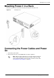
Mounting Power-1 in a Rack Mounting Power-1 in a Rack Mount the system in the rack with the network ports facing the front of the rack. Figure 2-1 Installing Power-1 Connecting the Power Cables and Power On 1. Connect the power cables. 2. On the back panel, turn on the Power button to start the appliance. Note - When a power supply fails or is not connected to the outlet, an alarm sounds continuously.
Using the First Time Configuration Wizard 3. Wait for the appliance to initialize and boot. The status of the appliance appears on the LCD screen: The appliance is ready for use when the model number is displayed. Using the First Time Configuration Wizard 1. Connect a standard network cable to the appliance's management interface and to your management network. The management interface is marked Internal. This interface is preconfigured with the IP address 192.168.1.1. 2.
Using the First Time Configuration Wizard 8. 9. 10. 11. 12. 13. Click Next. Configure Network Connections in the Network Connections page. If you modify the Mgmt address, a secondary interface is automatically created to preserve connectivity. This secondary interface can be removed on the Network > Network Connections page after the wizard is completed. Click Next. Configure Routing on the Routing Table page. Click Next. Set the Host and Domain on the Host and Domain Name page.
Creating the Power-1 Object in SmartDashboard c Click Finish to complete the First Time Configuration Wizard. The machine will automatically restart (this may take several minutes). Note - It is recommended to backup the system configuration. The backup menu can be accessed via the WebUI interface under the Appliance menu. For further details, see the Power-1 Administration Guide included on the CD.
Advanced Configuration Connecting to the Power-1 CLI You can connect to the command line interface of the Power-1 appliance using: The provided serial console cable (DTE to DTE) and terminal emulation software such as HyperTerminal (from Windows) or Minicom (from Unix/Linux systems). Connection parameters for Power-1 appliances are: 9600bps, no parity, 1 stop bit (8N1). An SSH connection to the management interface (if sshd is configured).
Chapter 3 Power-1 Hardware This chapter provides instructions for installing and removing hardware components on the Power-1 appliance.
Front Panel Components Front Panel Components This section describes the features and components located on the appliance front panel.
Front Panel Components Power-1 9070 Front Panel Key Description 1 LCD display screen 2 Management connection port - Ethernet connection to a remote management workstation 3 Synchronization port - for synchronizing with cluster members or a high availability peer 4 Console port - for a serial connection to the appliance using a terminal emulation program such as HyperTerminal 5 Screen operation keys 6 Power indicator LED 7 USB ports 8 Future expansion slot 9 Expansion line card exp1 (2 o
Front Panel Components Power-1 5070 Front Panel Key Description 1 LCD display screen 2 Management connection port - Ethernet connection to a remote management workstation 3 Synchronization port - for synchronizing with cluster members or a high availability peer 4 Console port - for a serial connection to the appliance using a terminal emulation program such as HyperTerminal 5 Screen operation keys 6 Power indicator LED 7 USB ports 8 Future expansion slot 9 Expansion line card exp (2 or
Front Panel Components Menu Sub-menu Purpose Set Internal IP Set the management interface IP address or Set Mgmt IP Set Netmask (cannot be edited when DHCP is enabled) Set the management interface network mask (cannot be edited when DHCP is enabled) Set Default GW Set the management interface default gateway (cannot be edited when DHCP is enabled) System Reboot Reboot the appliance LCD Panel Keys To Press Enter the main menu Navigate the menu or Select a menu option Go back to previous menu Whe
Front Panel Components Expansion Line Cards The Power-1 appliance contains optional expansion slots that accommodate cold-swappable network line cards. Power-1 5070 supports one network expansion slot Power-1 9070 supports two network expansion slots According to type, each expansion line card contains two or four ports.
Rear Panel Components Power-1 9070 and 11000 series models contain two hot-swappable redundant hard disk drives (RAID1). Figure 3-3 Hard Disk Drives RAID1 Mirroring Implemented by a dedicated RAID controller, the Power-1 9070 model performs RAID1 mirroring across two hard disk drives. Mirror rebuild is automatic. Rear Panel Components This section describes components located on the rear panel of the appliance. Main Power Switch The main power switch controls power to the entire unit.
Rear Panel Components Redundant Power Supply Units Located at the right rear of the appliance, two hot-swappable power supply units provide built-in power redundancy. Each power supply connects to an electric outlet. Figure 3-4 Redundant Power Supply Units When a power supply fails or is not connected to the outlet, an alarm sounds continuously. Cooling Fans The Power-1 appliance contains three replaceable cooling fans.
Customer Replaceable Parts Customer Replaceable Parts To ensure maximum availability and ease of maintenance, the Power-1 appliance contains the following customer replaceable parts: Power-1 5070 Power-1 9070 Power-1 11000 Series Power supplies 2 2 2 Cooling fans 3 3 3 Expansion line cards 1 1 with additional slot 1 with additional slot Hard disk drives 1 2 (RAID-1) Hot swappable 2 (RAID-1) Hot swappable Unless directed to do so by Check Point technical support, customers are prohibited
Customer Replaceable Parts Power Supply This section presents the procedures for removing and installing a power supply unit. Power-1 appliance contains two redundant power supplies. Figure 3-5 Redundant Power Supply Units Removing the Power Supply To remove a power supply unit: 1. 2. 3. 4. If the alarm sounds, press the red alarm button to the right of the power supply. The alarm stops. Remove the power cord. Loosen the retaining screw located above the power socket.
Customer Replaceable Parts Cooling Fan This section presents the procedures for removing and installing a fan unit. The Power-1 appliance contains three cooling fans. It is not necessary to power off the appliance before adding or removing a fan unit. Figure 3-6 Cooling Fans Removing Fan Units To remove a fan unit: 1. Loosen the four retaining screws in the corners of the fan assembly. 2. Gently pull the fan unit out of the appliance. Installing Fan Units To install a fan unit: 1.
Customer Replaceable Parts Important - Make certain that you are electromagnetically grounded when performing the following procedures. Static electricity can damage the appliance. Figure 3-7 Expansion Line Card Removing Expansion Line Cards To remove an expansion line card: 1. Power off the appliance and remove the power cords from the power supply units. 2. Loosen the retaining screws on either side of the expansion line card. 3. Holding the screws, pull the expansion line card out of the slot.
Customer Replaceable Parts Figure 3-8 Hard Disk Drives Removing a Hard Disk Drive To remove a hard disk drive: 1. Power-1 5070 only: Hard disk drive is not hot-swappable. Turn off the appliance and remove the power cords from the power supply unit before attempting to remove the hard disk drive. 2. Using the key supplied in the toolkit, unlock the drive. 3. Slide the release latch toward the left (see the arrow in diagram). The extraction handle pops out. 4.
Chapter 4 Restoring Factory Defaults As part of the troubleshooting process, it may be necessary to restore the Power-1 appliance to its factory default settings. You can restore your Power-1 appliance to the factory default image using one of the following methods: Using the WebUI Through the console boot menu Using the LCD panel Important - Restoring factory defaults deletes all information on the appliance.
Restoring Using the LCD Panel 7. During the Power-1 boot process, text similar to that shown below appears: Figure 4-9 Activating the Boot menu in HyperTerminal 8. At this point, you have approximately four seconds to hit any key to activate the Boot menu. 9. The Boot menu opens. Scroll to the relevant Reset to factory defaults image and press Enter. Restoring Using the LCD Panel To restore the Power-1 appliance to its default factory configuration using the LCD Panel keys: 1.
Restoring Using the LCD Panel Pressing any other button causes the Action Canceled message to display: At this point, pressing any key returns you to the boot menu. 6. Once you have confirmed the reset, wait for the appliance to restore the factory image. While the appliance is restored to the default image, a Reverting image don't turn off message displays continuously. When the appliance has been restored to its default factory configuration, the appliance reboots and the initializing message appears.
Chapter 5 Registration and Support In This Chapter Registration Support Where To From Here? 31 31 31 Registration Power-1 requires a specific Check Point license. Obtain a license and register at the Check Point Appliance Registration site (http://register.checkpoint.com/cpapp). Support For additional technical information about Check Point products, consult the Check Point Support Center (http://supportcenter.checkpoint.com).