Check Point VSX NGX R67 Administration Guide 20 February 2012 Classification: [Protected]
© 2012 Check Point Software Technologies Ltd. All rights reserved. This product and related documentation are protected by copyright and distributed under licensing restricting their use, copying, distribution, and decompilation. No part of this product or related documentation may be reproduced in any form or by any means without prior written authorization of Check Point. While every precaution has been taken in the preparation of this book, Check Point assumes no responsibility for errors or omissions.
Important Information Latest Software We recommend that you install the most recent software release to stay up-to-date with the latest functional improvements, stability fixes, security enhancements and protection against new and evolving attacks. Latest Documentation The latest version of this document is at: http://supportcontent.checkpoint.com/documentation_download?ID=10165 For additional technical information, visit the Check Point Support Center (http://supportcenter.checkpoint.com).
Contents Important Information .............................................................................................3 Introduction to VSX ................................................................................................9 Product Names.................................................................................................... 9 VSX Glossary .....................................................................................................10 VSX Overview ......................
Working with VSX Gateways ..............................................................................32 Creating a New VSX Gateway .......................................................................32 Modifying VSX Gateway Definitions ...............................................................37 Deleting a VSX Gateway ...............................................................................41 VSX Gateway Recovery ..............................................................................
VSX High Availability ..........................................................................................85 VSX Gateway High Availability ......................................................................85 Per Virtual System High Availability ...............................................................85 Virtual System Load Sharing (VSLS) ..................................................................86 Requirements ..........................................................................
Link Aggregation Overview ...............................................................................130 Link Aggregation Terminology .....................................................................130 How Link Aggregation Works .......................................................................131 High Availability Overview ............................................................................131 Load Sharing Overview.......................................................................
Migrating from an Open Server to a VSX-1 Appliance ......................................177 VSX Diagnostics and Troubleshooting ............................................................. 179 Introduction ......................................................................................................179 General Troubleshooting Steps ........................................................................179 Troubleshooting Specific Problems ..........................................................
Chapter 1 Introduction to VSX In This Chapter Product Names VSX Glossary VSX Overview How VSX Works Key Features and Benefits Typical VSX Deployments 9 10 10 11 12 13 Product Names Explanations and procedures included in this Administration Guide can apply to several brand names representing editions or variations of Check Point products. This document uses generic product names for variations of similar Check Point products.
Introduction to VSX VSX Glossary Term Definition VSX Virtual System Extension - Check Point virtual networking solution, hosted on a single computer or cluster containing virtual abstractions of Check Point Security Gateways and other network devices. These virtual devices provide the same functionality as their physical counterparts. VSX Gateway Physical server that hosts VSX virtual networks, including all virtual devices that provide the functionality of physical network devices.
Introduction to VSX How VSX Works Each "virtual" Security Gateway (known as a Virtual System in VSX terminology) functions as an independent firewall, protecting a specific network. Once packets arrive at the VSX gateway, it directs traffic to the Virtual System protecting the destination network. The Virtual System inspects all traffic and passes or rejects it according to rules contained in its Rule Base.
Introduction to VSX VSX Virtual Network Topology The example shows how a single VSX gateway, in this case containing four Virtual Systems, protects all four networks. Figure 1-2 A VSX gateway replaces multiple physical gateways Each Virtual System in a VSX environment works as an individual Security Gateway, providing the same security and networking functionality as a physical gateway. This example also shows: Four Virtual Systems, each handling packet traffic to and from discrete networks.
Introduction to VSX VSX QoS Enforcement provides the ability to control network quality of service in the VSX network environment by supporting the Differentiated Services (DiffServe) protocol and assigning different transmission characteristics to different classes of service. Non-Stop Security VSX supports the Check Point ClusterXL technology as well as third-party cluster solutions, such as Crossbeam, to guarantee nonstop security.
Introduction to VSX College campuses with many discrete networks for students, faculty and administration Any other large organization requiring multiple firewalls In each case, VSX provides access control, NAT, VPN, remote access, logging, and IPS services.
Chapter 2 VSX Architecture and Concepts In This Chapter Overview The VSX Gateway Virtual Devices VSX Management Overview VSX Traffic Flow VSX Routing Concepts VSX Clusters 15 15 18 22 25 27 30 Overview This chapter presents an overview of core VSX concepts and describes the architecture and building blocks that comprise a VSX virtual environment. This information is essential in order to plan, provision, configure, and operate a VSX virtual network deployment.
VSX Architecture and Concepts Local Management Connection When using a local management server (Security Management Server or Multi-Domain Security Management), all management traffic is handled by a dedicated management interface (DMI) that connects the management server with the VSX gateway. The dedicated management interface IP address can be either private or public.
VSX Architecture and Concepts Check Point recommends that remote management connections use a dedicated management interface (DMI) that connects directly to a router or switch that leads to the external network or the Internet. The following diagram illustrates this scenario. Figure 2-4 Typical VSX deployment with DMI remote management You can choose to use a non-dedicated management interface by connecting a Virtual Router or Virtual Switch to the management interface. This, however, is not recommended.
VSX Architecture and Concepts Provisioning and logging may degrade user performance Does not support several new VSX features Non-DMI is irreversible - you cannot change a non-DMI gateway to DMI Virtual Devices This section describes virtual network components and their characteristics. Virtual System A Virtual System is a virtual security and routing domain that provides the functionality of a Security Gateway with full firewall and VPN facilities.
VSX Architecture and Concepts A typical bridge mode scenario incorporates an 802.1q compatible VLAN switch on either side of the VSX gateway. The Virtual System interfaces do not require IP addresses and it remains transparent to the existing IP network.
VSX Architecture and Concepts Virtual Switches By providing layer-2 connectivity, a Virtual Switch connects Virtual Systems and facilitates sharing a common physical interface without segmenting the existing IP network. As with a physical switch, each Virtual Switch maintains a forwarding table with a list of MAC addresses and their associated ports.
VSX Architecture and Concepts A Physical Interface connects the Virtual Switch to an external router leading to the Internet. VLAN Interfaces connect the Virtual Systems to the VLAN Switch, via A VLAN trunk. The VLAN switch connects to the protected networks. Physical Interfaces Physical interfaces connect a VSX gateway to internal and external networks, as well as to the management server.
VSX Architecture and Concepts Unnumbered Interfaces VSX allows you reduce the number of IP addresses required for a VSX network deployment when using one or more Virtual Routers. A Warp link connected to a Virtual Router can "borrow" an existing IP address from another interface, instead of assigning a dedicated address to the interface leading to a Virtual Router. This capability is known as an Unnumbered Interface.
VSX Architecture and Concepts Note - According to the Check Point EULA (End User License Agreement), a Security Gateway can only manage security policies for Virtual Systems belonging to a single legal entity. In order to manage Virtual Systems belonging to multiple legal entities, you need to deploy a Multi-Domain Security Management management solution with a separate Domain Management Server for each legal entity. For more information regarding Licensing, refer to your Check Point Reseller.
VSX Architecture and Concepts Description 1 SmartDomain Manager 2 Multi-Domain Server 3 SmartDashboard 4 Domain Management Server 5 Main Domain Management Server 6 VSX Gateway 7 VSX Virtual System in Domain Management Servers Using the SmartDomain Manager, you provision and configure Domains and Domain Management Servers. Each Domain Management Server uses its own SmartDashboard instance to provision and configure its Virtual Systems, virtual devices, and security policies.
VSX Architecture and Concepts VSX Traffic Flow Overview A VSX gateway processes traffic according to the following steps: Context determination Security enforcement Forwarding to destination Context Determination VSX incorporates VRF (Virtual Routing and Forwarding) technology that allows creation of multiple, independent routing domains on a single VSX gateway or cluster. The independence of these routing domains makes possible the use of virtual devices with overlapping IP addresses.
VSX Architecture and Concepts Connection via a Virtual Switch Traffic arriving via a Virtual Switch passes to the appropriate Virtual System based on the destination MAC address, as defined in the Virtual Switch forwarding table. Traffic arrives at the Virtual System via the Warp Link associated with the designated MAC address.
VSX Architecture and Concepts Connection via a Virtual Router Traffic arriving via a Virtual Router passes to the appropriate Virtual System based on entries in the Virtual Router routing table. Routing may be destination-based, source-based or both. Traffic arrives to the designated Virtual System via its warp link.
VSX Architecture and Concepts The figure below presents an example of how Virtual Systems connected to a Virtual Switch and a physical VLAN switch communicate with each other. In this example, a host in VLAN 100 sends data to a server located in VLAN 200. Figure 2-12 Routing of virtual traffic between Virtual Systems 1. Traffic from the VLAN 100 host arrives at the VLAN switch, which inserts a VLAN tag and passes it to the VSX gateway via a VLAN trunk. 2.
VSX Architecture and Concepts Overlapping IP Address Space VSX facilitates connectivity when multiple network segments share the same IP address range (IP address space). This scenario occurs when a single VSX gateway protects several independent networks that assign IP addresses to endpoints from the same pool of IP addresses. Thus, it is feasible that more than one endpoint in a VSX environment will have the identical IP address, provided that each is located behind different Virtual System.
VSX Architecture and Concepts Limitations Source-based routing does not support overlapping IP addresses. Anti-spoofing protection is not effective for packets origination form a shared internal interface because there is no physical or logical segregation of traffic. In this case, it is recommended that you deploy antispoofing protection on the router itself. NAT Virtual Systems support Network Address Translation (NAT), much in the same manner as a physical firewall.
VSX Architecture and Concepts High Availability VSX provides for high system availability by ensuring transparent failover for VSX gateways and/or for individual Virtual Systems. If the active VSX gateway member fails, all sessions continue to run, securely and without interruption, on a standby cluster member. If an individual Virtual System fails, you can configure that Virtual System to fail over to a standby member while all other Virtual Systems continue to function on the active VSX gateway member.
Chapter 3 Configuring VSX In This Chapter Overview Working with VSX Gateways Working with Virtual Systems Working with Virtual Switches Working with Virtual Routers Working with Interface Definitions Working with Authentication Client/Session Authentication Working with Network Address Translation Tracking Activity with SmartView Monitor 32 32 42 51 53 60 63 66 68 69 Overview This chapter explains how to provision, configure and manage a VSX virtual network environment.
Configuring VSX To use the VSX Gateway wizard: 1. Open SmartDashboard. If you are using Multi-Domain Security Management, open SmartDashboard from the Domain Management Server of the VSX gateway. 2. In the Network Objects tab in the Objects Tree, right-click Check Point and select New Check Point. 3. Select the VSX type and then select Gateway. The VSX Gateway Wizard opens, showing the General Properties page.
Configuring VSX Shared Interface: Virtual systems share one external interface, but maintain separate internal interfaces. Separate Interfaces: Virtual systems use their own separate internal and external interfaces. This template creates a Dedicated Management Interface (DMI) by default. If the default templates are not appropriate, you can create a custom configuration: Custom Configuration: Define Virtual System, Virtual Router, Virtual Switch, and Interface configurations.
Configuring VSX Defining Physical Interfaces In the VSX Gateway Interfaces window, define physical interfaces as VLAN trunks. The table shows the interfaces currently defined on the gateway machine. To define an interface as a VLAN trunk, select VLAN Trunk. Virtual Network Device Configuration If you chose the Custom Configuration option, the Virtual Network Device Configuration window opens. In this window, define a Virtual Device with an interface shared with the VSX gateway.
Configuring VSX Important - This setting cannot be changed after you complete the VSX Gateway Wizard. If you define a non-DMI gateway, you cannot change it to a DMI gateway later. 4. Define the IP address and Net Mask for a Virtual Router. These options are not available for a Virtual Switch. 5. Optionally, define a Default Gateway for a Virtual Router (DMI only). VSX Gateway Management In the VSX Gateway Management window, define security policy rules that protect the VSX gateway.
Configuring VSX Completing the VSX Wizard Click Next to continue and then click Finish to complete the VSX Gateway wizard. This may take several minutes to complete. A message shows successful or unsuccessful completion of the process. If the process ends unsuccessfully, click View Report to see the error messages. See the Troubleshooting chapter ("VSX Diagnostics and Troubleshooting" on page 179).
Configuring VSX Color - Color of the object icon as it appears in the Object Tree. Secure Internal Communication - Check and re-establish SIC trust. Check Point Products - Select Check Point products for this gateway. Secure Internal Communication (SIC) Test and reset SIC trust and also see the VSX gateway Relative Distinguished Name. To manage SIC, click Communication. The Trusted Communication window opens. To initialize SIC trust, click Initialize.
Configuring VSX VSX Gateway - Creation Templates The Creation Templates page displays the creation template used to create the virtual systems for this Security Gateway. You can change from the current creation template to the Custom Configuration template and change the shared physical interface if the Shared Interface template is active. Select Custom Configuration to change from the Shared Interfaces or Separate Interfaces templates. This effectively overrides the default template.
Configuring VSX VSX Gateway - Topology The Topology page contains definitions for interfaces and routes between interfaces and virtual devices. Interfaces The Interfaces section defines interfaces and links to devices. You can add new interfaces as well as delete and modify existing interfaces. To add an interface, click Add. The Interface Properties window opens. Select an interface from the list and define the appropriate properties ("Modifying an Interface Definition" on page 63).
Configuring VSX Note - If you wish to enable anti-spoofing protection when there are no routes pointing to internal networks, disable the Calculating topology option and modify the appropriate interface definitions to enable antispoofing. VSX Gateway - NAT This page contains various NAT options that are not relevant for VSX gateways. VSX Gateway - VPN The VPN page contains a variety of configuration properties for VSX gateways in site-to-site VPN deployments.
Configuring VSX VSX Gateway Recovery In the event of a catastrophic VSX gateway failure, you can use the vsx_util command to restore the VSX gateway configuration as well as its virtual device configuration. 1. Reinstall the gateway and configure IP, net mask and default gateway. 2. Verify that all management interfaces have the same IP addresses as before. 3. From a command line interface on the management server, run vsx_util reconfigure to restore the previous configuration.
Configuring VSX 2. In the Network Objects tab, located in the Objects Tree, right-click Check Point and select New Check Point > VPN-1 Power VSX > Virtual System. The VSX Gateway Wizard opens, displaying the General Properties page. Defining General Properties The General Properties wizard page contains properties that define the Virtual System object and the hosting VSX gateway. This window contains the following properties: Name: Unique, alphanumeric for the VSX gateway.
Configuring VSX Shared Interface or Separate Interfaces The Virtual System Network Configuration page for the Shared Interface and Separate Interfaces templates appears as shown. To configure the external and internal interfaces: 1. Select the desired interfaces from the appropriate list. 2. If the selected Interface is a VLAN interface, enter the VLAN tag in the appropriate field. This field is not available for non-VLAN interfaces. 3. Enter the IP address and net mask in the appropriate fields.
Configuring VSX To configure the external and internal interfaces: 1. Select the desired interfaces for the internal and external networks from the appropriate list. If the selected Interface is a VLAN interface, enter the same VLAN tag in both the external and internal VLAN Tag fields. This field is not available for non-VLAN interfaces. 2. Define the topology for the internal interface as follows: Select Not Defined if you do not wish to define an IP address.
Configuring VSX To configure the external and internal interfaces: 1. In the interface table, define interfaces. You can add new interfaces as well as delete and modify existing interfaces. To add an interface, click Add. The Interface Properties window opens. Select an interface from the list and define the appropriate properties. Click Help for details regarding the various properties and options. 2. Select the Main IP Address from the list.
Configuring VSX Completing the Definition Click Next and then Finish to create the Virtual System. Please note that this may take several minutes to complete. A message appears indicating successful or unsuccessful completion of the process. If the process ends unsuccessfully, click View Report to view the error messages. Refer to the troubleshooting chapter ("VSX Diagnostics and Troubleshooting" on page 179) for further assistance.
Configuring VSX Virtual System - Topology The Topology page contains definitions for Virtual System interfaces, routes and Warp links. Based on these interface settings, VSX automatically creates routes to Virtual Devices and the VSX gateway. Note - If you modify the topology for a specific Virtual System in a cluster environment, the cluster topology is not updated until you install a policy on that Virtual System. Interfaces: The Interfaces table defines interfaces and links to devices.
Configuring VSX VPN Domain: The VPN Domain defines the set of hosts located behind a given Virtual System that communicate via a VPN tunnel with peer Virtual Systems. These options are only available if you selected VPN in the Check Point Products section on the General Properties page. When including a virtual device as part of a VPN connection, you must specify a VPN Domain. The domain definition specifies Virtual System interfaces that are included in the VPN.
Configuring VSX Virtual System - Remote Access The Remote Access page contains properties that govern establishing VPN connections with Remote Access clients. This window is only available if the Check Point VPN product is enabled on the General Properties page. Please refer to the online help and the R75 VPN Administration Guide (http://supportcontent.checkpoint.com/documentation_download?ID=11675) for further details regarding VPN with Remote Access clients.
Configuring VSX Virtual System - Advanced These pages contain a variety of configuration options for SNMP, connection persistence and permissions to install policies. For further information regarding these options, please refer to the online help and the R75 IPS Administration Guide (http://supportcontent.checkpoint.com/documentation_download?ID=11663). Deleting a Virtual System To delete a Virtual System, right-click the appropriate Virtual System object on the Object Tree and select Delete.
Configuring VSX Defining the General Properties The General Properties page contains properties that identify the Virtual Switch and the VSX gateway or cluster to which it connects. This window contains the following properties: Name: Unique name containing only alphanumeric characters, the hyphen and underscore characters. VSX Gateway/Cluster: Select a VSX gateway or cluster from the list. Defining the Network Configuration The Network Configuration page defines the Virtual Switch interface.
Configuring VSX Virtual Switch - General Properties The General Properties page allows you to add comments and change the icon color as displayed in SmartDashboard. Virtual Switch - Topology The Topology page defines Virtual Switch interfaces. You can only modify the single defined interface. Warp interfaces cannot be modified from this window. To add an interface, click Add. The Interface Properties window opens.
Configuring VSX You can define Virtual Routers for both external and internal communications. A Virtual Router that connects to external networks, including a DMZ and the Internet, are referred to as an external Virtual Router. A Virtual Router that connects to internal, protected networks is known as an internal Virtual Router.
Configuring VSX Creating a New Virtual Router You use the Virtual Router Wizard to create a new Virtual Router. You can modify the initial definition and configure advanced options after completing the wizard. The definition procedure consists of two steps, each represented by a wizard window: To create a new Virtual Router using the wizard: 1. Open SmartDashboard.
Configuring VSX To add an interface, click Add. The Interface Properties window opens. Select an interface from the list and define the IP address, net mask and other properties. Refer to Modifying an Interface Definition or the online help for details regarding the various properties and options. Routes: Add network routes between this Virtual router, Virtual Systems, external network devices and network addresses.
Configuring VSX Virtual Router - Topology The Virtual Router Network Configuration page defines the network topology for the Virtual Router. For an external interface, you define one or more shared external interfaces and a default gateway. The topology definition consists of the following properties: Interfaces: Add new interfaces, or modify or delete existing interfaces. To add an interface, click Add. The Interface Properties window opens.
Configuring VSX Deleting a Virtual Router You cannot delete a Virtual Router if it is still connected to a Virtual System. Remove all Virtual Router connections before deleting. To delete a Virtual Router, right-click the appropriate Virtual Router object on the Object Tree and select Delete. Click Yes in the confirmation box.
Configuring VSX 2. Click Add to define a new rule or Edit to modify an existing rule. The Add/Edit Route Rule window appears. Define the following properties as required: Source IP Address and Net Mask Destination IP Address and Net Mask (optional) Next Hop Gateway: Select a Virtual System from the list. Working with Dynamic Routing This section presents procedures for configuring dynamic routing for Virtual Systems and Virtual Routers.
Configuring VSX Working with Interface Definitions All VSX gateways and Virtual Routers and Virtual Switches contain at least one interface definition. Typically, you define the interfaces during the process of configuring the topology for a given object. Warp interfaces, however, are created automatically based on virtual device definitions and their topology. You cannot modify or delete a Warp interface.
Configuring VSX Configuring Connections Leading to Virtual Routers The General tab for interface connections leading to Virtual Routers contains connection properties specific to Virtual Routers. Leads to: Select a Virtual Router from the list. Numbered Interface: Select this to assign a dedicated Virtual System IP address to an interface leading to a Virtual Router. Select a Virtual System address from the list. The net mask property is always defined as 255.255.255.
Configuring VSX External: The interface leads to external networks or to the Internet. Internal: The interface leads to internal networks and/or a DMZ and includes the following properties: Not Defined: IP routing is not defined for this device. Network: Routing is defined by the IP and net mask defined in General Properties. Specific: Routing is defined by a specific network or network group.
Configuring VSX 6. Close the window and save the definition. 7. Add a rule to the Rule Base that allows traffic for the specified multicast groups and install the policy. Modifying an Interface Definition This sections presents procedures for modifying existing interface definitions and related features. Selecting and Opening an Existing Interface Interfaces definitions are always associated with a Virtual Gateway or a Virtual System definition. To work with an existing interface definition: 1.
Configuring VSX SecurID SecurID requires users to possess a token authenticator and to supply a password. Token authenticators generate one-time passwords that are synchronized to an RSA ACE/server. Hardware tokens are key-ring or credit card-sized devices, while software tokens reside on the PC or device from which the user wants to authenticate. All tokens generate a random, one-time use access code that changes approximately every minute.
Configuring VSX Private: Servers are accessible from Virtual Systems In both instances, the SecurID ACE/Server sends a shared key (called a "node secret") to its peer ACE/Clients. This key is unique per IP address, and is sent once for each IP address. Note - Users cannot authenticate to a Virtual System using SecurID when SSL Network Extender and SecureClient are active. Shared To configure the shared option, use the database tool GUIDBedit to set the shared_external_server property to TRUE.
Configuring VSX CLIENT_IP= 3. Perform cpstop/cpstart. Perform the following procedure on all cluster members: 4. Open the /etc/services file for editing. 5. Add the following lines: securid 5500/udp securidprop 5510/tcp The Effect of Upgrading on Authentication Processes An existing Virtual System that has been upgraded to the current version, receives the default settings for authentication with external servers.
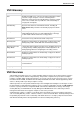
Configuring VSX 2. Open $FWDIR/conf/cpauthd.conf , on the VSX Gateway machine using a text editor. 3. Add or modify the following attributes according to the table: Attribute Default Value Explanation clauth_port 259 The TCP port on which client authentication over TELNET is done. 0 = Client authentication over TELNET is disabled. clauth_http_port 900 The TCP port on which client authentication over HTTP/HTTPS is done. 0 = Client authentication over HTTP/HTTPS is disabled.
Configuring VSX Configuring Authentication for Specific Virtual Systems To configure client/session authentication for the VSX Gateway: 1. Backup $FWDIR/CTX/CTX#/conf/cpauthd.conf, where CTX# refers to the specific Virtual System directory. 2. Delete the original $FWDIR/CTX/CTX#/conf/cpauthd.conf. 3. Open $FWDIR/conf/cpauthd.conf to FWDIR/CTX/CTX#/conf/cpauthd.conf using a text editor. 4.
Configuring VSX Configuring NAT You configure NAT using the NAT page in the Virtual System window. Hide or Static NAT addresses configured in this manner are automatically forwarded to the Virtual Router to which the Virtual System is connected. Alternatively, you can manually add NAT routes on the Topology page in the Virtual Router window. To enable and configure NAT for a Virtual System: 1. Enable the Add Automatic Address Translation option. 2. Select a translation method from the list.
Chapter 4 Using VSX with Multi-Domain Security Management You can manage a VSX deployment using Multi-Domain Security Management. This chapter assumes that you are familiar with the Multi-Domain Security Management product. Only procedures specific to VSX deployments are discussed. See the R75 Multi-Domain Security Management Administration Guide (http://supportcontent.checkpoint.com/documentation_download?ID=11683).
Using VSX with Multi-Domain Security Management Description 1 SmartDomain Manager 2 Multi-Domain Server 3 SmartDashboard 4 Domain Management Server 5 Main Domain Management Server 6 VSX Gateway 7 VSX Virtual System in Domain Management Servers The Multi-Domain Server is a central management server that hosts the network management and security policy databases for these networks. Each independent domain is represented by a Domain, which provides the full functionality of a Security Gateway.
Using VSX with Multi-Domain Security Management Multi-Domain Log Server licenses are available in packs of 10, 25, 50, 100 and 250. This license is bound to the Multi-Domain Log Server IP address. Domain Log Server License: This license is intended for a single Domain with log files hosted only on the Multi-Domain Server. The license is bound to the Log Servers IP address. Individual Log Servers licenses are not required for Log Servers hosted on an Multi-Domain Log Server.
Using VSX with Multi-Domain Security Management Limitations of VSX/Domain Management Server Bundle Licenses Bundle licenses only cover Virtual Systems. If you wish to mix physical devices (Security Gateways, etc.) and Virtual Systems on one Domain Management Server, you must also add the appropriate regular Domain Management Server licenses. Virtual Systems installed on a mixed Domain Management Server do not use any license "slots" from a regular license.
Using VSX with Multi-Domain Security Management For More Information For more information regarding licensing, refer to the Check Point User Center (http://usercenter.checkpoint.com). VSX Provisioning The procedures for provisioning and configuring VSX gateways, clusters and virtual devices using the MultiDomain Security Management model are essentially the same as described for the Security Gateway management model.
Using VSX with Multi-Domain Security Management Note - You must always define the first Multi-Domain Server as the primary Multi-Domain Server. Each additional Multi-Domain Servermust be defined as a secondary Multi-Domain Server. To define a Multi-Domain Server as a secondary station, respond 'no' to the prompt "Are you installing the Primary Multi-Domain Server [yes/no]?" during the initial configuration process. Once you complete the initial configuration, you cannot change this definition. 4.
Using VSX with Multi-Domain Security Management Status Checking Interval: Interval in seconds between Multi-Domain Server/Domain Management Server status checks (Default = 300). Secure Internal Communication Trust: Click Communication to open the 3. On the Licenses tab, add Multi-Domain Server licenses as required for your deployment. Click Add to add a new license or Fetch From File to import a license from a file. 4. Click OK to continue.
Using VSX with Multi-Domain Security Management Domain Properties Page Enter the Domain or business entity name, contact person name and contact person email in the appropriate fields on the Domain Properties page: Global Policy Page The Global Policy page defines how global policies are applied to a Domain Management Server. Global Policies are collections of rules and global objects that apply by default to the entire Multi-Domain Security Management environment or to defined groups of Domains.
Using VSX with Multi-Domain Security Management Global Objects When assigning a global policy to a Domain Management Server, you can choose to assign all global objects or to assign only those objects required by the global policy Rule Base. Select the appropriate option for this new Domain. IPS Enable the Subscribe Domain to IPS Service option to assign the global IPS policy to this Domain along with the global policy.
Using VSX with Multi-Domain Security Management To assign permissions: 1. Select an administrator in the Not Assigned column and click Add or select an administrator in the Assigned window and click Permissions. The Edit Administrator's Domain-Level Permissions window opens. 2. Select the Customized option to customize administrator permissions, and enable or disable individual task permissions as appropriate. Refer to the online help for details regarding individual options and task permissions.
Using VSX with Multi-Domain Security Management To assign an predefined GUI client to this Domain, select one or more GUI clients or groups from the Not Assigned column and click Add. The GUI client moves to the Assigned column. To remove an GUI client, select one or more GUI clients or groups from the Assigned column and click Remove. The administrator moves to the Not Assigned column. To define a new GUI client, click New GUI Client and configure the appropriate properties.
Using VSX with Multi-Domain Security Management Modifying Existing Domains and Servers To modify existing Domains and Domain Management Servers, double-click the object in the SmartDomain Manager General - Domain Contents view. The pages and properties are identical to those for creating a new Domain ("Creating a New Domain Object" on page 76).
Chapter 5 Introduction to VSX Clusters This chapter presents a conceptual overview of VSX cluster deployments, with emphasis on clustering features and their application. This discussion assumes that the reader is familiar with network cluster applications and environments, particularly ClusterXL. The Cluster Management chapter ("Managing VSX Clusters" on page 93) provides detailed configuration procedures, including instructions for enabling and using all VSX clustering features.
Introduction to VSX Clusters Internal networks send traffic destined for the Internet or external networks, to the cluster IP address. This traffic is processed by the designated cluster member, inspected, and forwarded to its external destination. Each member interface has a unique, physical IP addresses.
Introduction to VSX Clusters VSX Cluster Architecture VSX IP address allocation is similar to physical networks. Both real and virtual IP addresses are required for network connectivity (internal and external), management, and state synchronization. VSX simplifies the IP address management task by automatically assigning IP addresses to Warp Links between virtual devices.
Introduction to VSX Clusters VSX High Availability This section describes VSX high availability features. In a VSX environment, you can work with one of two high availability scenarios: VSX Gateway High Availability: Each cluster member functions as a VSX gateway and is synchronized with the other members. If one member goes down, it immediately fails over to another member.
Introduction to VSX Clusters Note - The following virtual devices are not supported when the Per Virtual System state is enabled: Virtual Routers Virtual Switches without physical or VLAN interfaces Virtual System Load Sharing (VSLS) VSX clusters can efficiently balance your network traffic load by distributing active virtual systems amongst cluster members.
Introduction to VSX Clusters VSLS allows the administrator to either manually place specific Virtual Systems on specific cluster members, or allow the system to determine the dispersal configuration automatically. Refer to ("Configuring Virtual System Load Sharing" on page 113). Note - You cannot configure a VSX ClusterXL in the Load Sharing mode if the cluster contains Virtual Systems in bridge mode or Virtual Routers.
Introduction to VSX Clusters Virtual System States VSLS adds a backup state to the existing active and standby states. The backup state contains the latest configuration settings for each Virtual System, but does not receive state table synchronization. The relationship between Virtual System states is illustrated in the below figure. Figure 5-23 State synchronization Each Virtual System peer in a VSLS cluster is replicated on all cluster members, and each copy exists in a different state.
Introduction to VSX Clusters Systems, which are fully synchronized with their active peers, change immediately to the active state and preserve active connections. At the same time, the backup Virtual Systems switch to standby, and synchronize fully with the newly active Virtual Systems. In this scenario, Member 1 fails and its active and standby Virtual Systems fail over to Members 2 and 3. The active Virtual System (VS1) moves to Member 2 and directs all VS 1 traffic itself.
Introduction to VSX Clusters Failure Recovery When the failed cluster member or Virtual System comes back online, the system returns to its original load sharing configuration. Bridge Mode By implementing native layer-2 bridging instead of IP routing, you can add Virtual Systems without adversely affecting the existing IP structure. When in the Bridge mode, Virtual System interfaces do not require IP addresses.
Introduction to VSX Clusters Deployment Scenarios This section presents illustrative Active/Standby Bridge mode deployments, which cannot function using a standard STP Bridge mode configuration. VLAN Shared Interface Deployment In this deployment, each individual member connects to pair of redundant switches via a VLAN trunk. All Virtual Systems in a given member share the same VLAN trunk. The following figure illustrates example of such a deployment with active, standby and backup members.
Introduction to VSX Clusters VSX, using the Active/Standby Bridge mode, is incorporated into the distribution layer, enforcing the security policy. This is illustrated in the following figure: Figure 5-27 Active/Standby bridge mode - core network The routers direct external, "dirty" traffic to the appropriate Virtual System via a segregated VLAN. Filtered, "clean" traffic exits the Virtual System via a separate segregated VLAN back to the routers and on to internal destinations.
Chapter 6 Managing VSX Clusters This chapter presents the procedures for configuring VSX in various cluster deployment scenarios. In addition to the basic scenarios, conceptual material and illustrative examples are presented for several advanced features, including the Bridge mode and dynamic routing.
Managing VSX Clusters Defining Cluster General Properties The Cluster General Properties page contains basic identification properties for VSX gateways. This window contains the following properties: VSX Cluster Name: Unique, alphanumeric for the cluster. The name cannot contain spaces or special characters except the underscore. VSX Cluster IP Address: Management interface IP address. VSX Cluster Version: VSX version to use for this cluster.
Managing VSX Clusters You always have the option of overriding the default creation template when creating or modifying a Virtual System The available creation templates are as follows: Shared Interface: All virtual systems share a single external interface, but maintain separate internal interfaces. Separate Interfaces: All virtual systems use their own separate internal and external interfaces. This template creates a Dedicated Management Interface (DMI) by default.
Managing VSX Clusters To add a new member: 1. In the VSX Cluster Members window, click Add. The Member Properties window opens. 2. Enter the a unique member name and its IP address in the appropriate fields. 3. Enter and confirm the activation key to initialize SIC trust between the member and the management server. Defining Cluster Interfaces The VSX Cluster Interfaces window allows you define physical interfaces as VLAN trunks.
Managing VSX Clusters Configuring Cluster Members If you selected the custom configuration option, the VSX Cluster Members window appears. In this window, you define the synchronization IP address for each member. . To configure the cluster members: 1. Select the synchronization interface from the list. 2. Enter the synchronization interface IP address and net mask for each member.
Managing VSX Clusters TCP: https (secure http) traffic Configuring the Cluster Security Policy 1. Allow: Enable a rule to allow traffic for those services for which you wish to allow traffic. Clear a rule to block traffic. By default, all services are blocked. For example, you may wish to allow UDP echo-request traffic in order to be able to ping cluster members from the management server. 2. Source: Click the arrow and select a Source Object from the list. The default value is *Any.
Managing VSX Clusters General Properties Use the General Properties page to view general properties and to activate Check Point products for use with this cluster and its members.
Managing VSX Clusters Cluster Members The Cluster Members page enables you to view and/or modify several properties for individual cluster members, including IP addresses for members and the internal communication network. You can also view where cluster and member objects in the object database are used. Gateway Cluster Member List This tab shows the currently defined cluster members. Double-click on a member or select a member and click Edit to open its Cluster Member Properties window.
Managing VSX Clusters Where Used Click Where used to display information relating to the selected member in the objects database. The following data appears in the window: Name: Cluster name. Table: Name of the table in the database under which the selected object is listed. Is removable: Specifies whether or not you are allowed to remove the selected object. If the object is not removable and nevertheless you choose to remove it, it will impact the database or rule base.
Managing VSX Clusters Creation Templates The Creation Templates page displays the creation template used to create Virtual Systems. You can change from the current creation template to the Custom Configuration template and change the shared physical interface if the Shared Interface template is active. Select the Custom Configuration option to change from the Shared Interfaces or Separate Interfaces templates.
Managing VSX Clusters Topology The Topology page contains interface and routing definitions. Interfaces The Interfaces section defines interfaces and links to devices. You can add new interfaces as well as delete and modify existing interfaces. To add an interface: 1. Click Add. 2. In In the Interface Properties window, select an interface from the list and define the appropriate properties ("Modifying an Interface Definition" on page 63).
Managing VSX Clusters 2. In the Route Configuration window, modify the IP address, net mask and next hop parameters as necessary. 3. Enable or clear the Propagate route to adjacent Virtual Devices option as necessary. Click Help for details regarding the various properties and options. Calculating topology automatically based on routing information Enable this option to allow VSX to automatically calculate the network topology based on interface and routing definitions (enabled by default).
Managing VSX Clusters In the Set VPN Domain window, select a VPN domain from the list or click New to define a new domain. Click OK in both windows to continue. NAT The Advanced page allows you to configure NAT for Virtual Systems connected to a Virtual Router. To enable and configure NAT: 1. Enable the Add Automatic Address Translation option. 2. Select a translation method from the list. Hide NAT: Hide NAT only allows connections originating from the internal network.
Managing VSX Clusters Please refer to the online help and the R75 VPN Administration Guide (http://supportcontent.checkpoint.com/documentation_download?ID=11675) for further details regarding VPN concepts and configuration. Remote Access The Remote Access page contains properties that govern establishing VPN connections with Remote Access clients. This window is only available if the Check Point VPN product is enabled on the General Properties page.
Managing VSX Clusters Changing the Internal Communication Network IP You can change the internal communication network IP address by using the vsx_util change_private_net ("change_mgmt_private_net" on page 198) command. Working with Cluster Members This section presents procedures for adding and deleting cluster members, as well as for upgrading existing cluster members to VSX. Adding a New Member Important - Verify that no other administrators are connected to the management server before proceeding.
Managing VSX Clusters 8. Reboot the new member. If the cluster is running in the VSLS mode, run vsx_util vsls to redistribute Virtual Systems to the newly added member. Deleting a Member Important - Verify that no other administrators are connected to the management server before proceeding. The vsx_util command cannot modify the management database if the database is locked. You perform this operation using the management server command line.
Managing VSX Clusters section of the R75 SecurePlatform Administration Guide (http://supportcontent.checkpoint.com/documentation_download?ID=11666). Upgrading a Member to the Current Version Important - Verify that no other administrators are connected to the management server before proceeding. The vsx_util command cannot modify the management database if the database is locked. Performing the following steps to upgrade the cluster and its members: 1. Close SmartDashboard. 2. Enter the Expert mode. 3.
Managing VSX Clusters Notes to the Upgrade Process You only need to run the vsx_util upgrade command once for each VSX cluster. You must, however, run the vsx_util reconfigure command for each cluster member. For example, for a deployment with two clusters, each cluster having three members, run vsx_util upgrade twice, once for each cluster object, and the vsx_util reconfigure six times, once for each cluster member.
Managing VSX Clusters 2. Re-initialize the members using the cpstop and cpstart commands. Converting the Cluster To convert the cluster to HA: 1. Execute the vsx_util convert_cluster command . 2. Enter the Security Management Server or Multi-Domain Security Management Domain Management Server IP address. 3. From the Load Sharing menu, enter "3. Set all VSs active on one member". 4. Enter the administrator user name and password. 5. Enter the VSX cluster name. 6. Enter "HA" 7.
Managing VSX Clusters vsx_util convert_cluster ************************************************* Note: the operation you are about to perform changes the information in the management database. Back up the database before continuing.
Managing VSX Clusters Configuring New Cluster Members To configure members for VSX gateway high availability: 1. During the initial configuration phase (configsys), enter 'y' in response to the "Would you like to install a Check Point clustering product?" question to enable VSX clustering. 2. Enter 'n' when prompted to enable the Per Virtual System State. 3. Select the "ClusterXL" option. 4. Configure all other properties according to your requirements.
Managing VSX Clusters Enabling the Per Virtual System State Mode The Per Virtual System State mode enable active Virtual Systems to be placed on different cluster members, and for Virtual System-specific failover. This setting is mandatory for VSLS. On each cluster member, do the following: Note - The following virtual devices are not supported when the Per Virtual System state is enabled: Virtual Routers Virtual Switches that do not have physical or VLAN interfaces 1. Run cpconfig. 2.
Managing VSX Clusters 6. Export VSLS configurations to comma separated value (CSV) text files 7. Exporting and Import VSLS configurations from/to comma separated value (CSV) text files To work with the vsx_util vsls command: 1. Run vsx_util vsls from the Expert mode on the management server 2. Select the desired choice from the VSLS menu Enter Administrator Name: aa Enter Administrator Password: Enter VSX cluster object name: vsx VS Load Sharing - Menu ________________________________ 1.
Managing VSX Clusters Automatically assign weights only to Virtual Systems. This method prompts you for a weight for each Virtual System and then automatically updates the settings. Manually assign both priorities and weights to individual Virtual Systems. To Automatically assign weights to all Virtual Systems: 1. From the VSLS menu, select "Manually set priority and weight". 2. Enter "a" to automatically scroll through each Virtual System. 3.
Managing VSX Clusters Virtual System Priority Virtual System priority refers to a preference regarding which member hosts a Virtual System's active, standby, and backup states. This preference is expressed as an integer value, as shown in the following table. Priority Definition 0 Highest priority, indicating the member designated to host the Virtual System active state. 1 Second highest priority, indicating the member designated to host the Virtual System standby state.
Managing VSX Clusters VSLS Configuration File The VSLS configuration file is a comma separated value (CSV) text file that contains configuration settings for all Virtual Systems controlled by a management server. All lines preceded by the # symbol are comments and are not imported into the management database. # Check Point VSX - VS Load Sharing configuration file # # Administrator : aa # SmartCenter/Main Domain Management Server : 192.168.50.
Managing VSX Clusters command enables the action and the next occurrence disables it. These options his allow you to efficiently debug very long configuration files by displaying or logging only suspicious sections of the data. Command Action !comments Sequentially displays comment lines (those preceded with the '#' character) contained in the configuration file.
Managing VSX Clusters Enabling STP Bridge Mode when Creating Member When creating a new VSX gateway for use as a cluster member, configure the following cluster options during the initial configuration process (sysconfig or cpconfig): 1. Enter 'y' in response to the "Would you like to install a Check Point clustering product? question". 2. Enter 'n', if prompted, to disable the Active/Standby Bridge mode. Continue with the remainder of the initial configuration process.
Managing VSX Clusters Configuring a Cluster for PVST+ Load Sharing To configure a VSX cluster for PVST+ load sharing, perform the procedures described in the STP Bridge Mode section ("STP Bridge Mode" on page 119). Active/Standby Bridge Mode This section presents the procedures for enabling and configuring the Active/Standby Bridge mode for Virtual Systems and VSX gateways.
Managing VSX Clusters Configuring Virtual Systems for Active/Standby Bridge Mode To configure a Virtual System to use the Bridge mode, you must define it as a Virtual System in the Bridge mode when initially creating it. You cannot reconfigure an existing, non-Bridge mode Virtual System to use the Bridge mode at a later time. To configure a Virtual System for the Active/Standby Bridge mode: 1. On the Virtual System Wizard - General Properties page, enable the Bridge mode option. 2.
Managing VSX Clusters Source Cluster MAC Addresses Cluster members use CCP to communicate with each other. In order to distinguish CCP packets from ordinary network traffic, CCP packets are given a unique source MAC address. The first four bytes of the source MAC address are all zero: 00.00.00.00 The fifth byte of the source MAC address is a "magic" number, a number that encodes critical information in a way intended to be opaque.
Managing VSX Clusters To enable monitoring of all VLANs, enable the fwha_monitor_all_vlans property in $FWDIR/boot/modules/fwkern.conf. Note - Monitoring all VLANS is enabled automatically when the Per VLAN state option is enabled. Enabling Dynamic Routing Protocols ClusterXL supports Dynamic Routing (Unicast and Multicast) protocols as an integral part of the SecurePlatform VSX installation.
Managing VSX Clusters --------- Launch the Dynamic Routing Module vsx1:0]# router ER0 999 Unable to connect to host 'localhost'! ER0 999 Dynamic Routing is not supported on VSX gateway/cluster Use 'vrf-connect' to enter specific Virtual System (disconnected)>vrf-connect 1 localhost.localdomain- VRF-1>enable localhost.localdomain- VRF-1#configure terminal --------- Enable OSPF and provide an OSPF router ID localhost.localdomain- VRF-1(config)#router ospf 1 localhost.
Chapter 7 Working with URL Filtering In This Chapter Introduction Configuring URL Filtering 126 127 Introduction Access to the Internet can expose your organization to a variety of security threats and negatively affect employee productivity as a result of non-work-related surfing and downloading of files. Due to problems associated with employee web surfing, organizations are turning to Web Filtering to control employee Internet access, reduce legal liability and improve organizational security.
Working with URL Filtering Following category assignment, the Web Filtering engine then blocks or allows the traffic according to one or more of the following rule types: Network Exceptions: Override Web Filtering rules based on predefined combinations of source and destination locations. Address Rules: Traffic destined for specific URLs/IP addresses is either blocked or allowed according to a Blocked List (blacklist) or an Allowed List (white list).
Working with URL Filtering Note - The URL database also includes IP addresses. By Default, all IP addresses are allowed, even if included in the Allow or Block lists. To enable the Allow and Block lists to work with IP addresses, use the GuiDBedit utility and change the categorize_http_request_method parameter to host_dns_and_ip (the default value is host_dns). When defining IP addresses in the Allow or Block lists, you must append the '/' character to the end of each address string.
Working with URL Filtering Performing Manual Updates To perform a manual database update: 1. On the Database Updates page in the SmartDashboard Content Inspection tab, click Update databases now. The Update Databases wizard opens. 2. In the first window, enter your Check Point User Center email address and password in the appropriate fields. 3. In the second window, select Custom update. 4. In the third window, select URL Filtering. 5.
Chapter 8 Working with Link Aggregation In This Chapter Link Aggregation Overview Configuring Link Aggregation for High Availability Link Aggregation - Load Sharing Mode Changing the Bond Interface Mode Enslaving Interfaces to a Bond Detaching Interfaces from a Bond Deleting a Bond Changing an Existing Interface to a Bond Troubleshooting Bonded Interfaces 130 134 137 145 145 146 146 148 148 Link Aggregation Overview Link aggregation, also known as interface bonding, joins multiple physical interfaces toge
Working with Link Aggregation How Link Aggregation Works A bond contains a minimum of one and may contain up to eight slave interfaces. All slave interfaces contained in a bond share a common IP and MAC address. We recommend that each cluster member contain the same quantity of identical slave interfaces. Figure 8-29 Bond with three slave interfaces Note - Link Aggregation is only supported on Check Point SecurePlatform machines.
Working with Link Aggregation In this scenario: Member-1 and Member-2 are cluster members in the High Availability mode S-1 and S-2 are switches C-1, C-2, C-3 and C-4 are network connections Load Sharing Overview Load sharing provides the ability to spread traffic over multiple slave interfaces, in addition to providing interface redundancy. All interfaces are always active.
Working with Link Aggregation 2. The bond initiates failover to a standby interface. Since this is a failover within the bond, the status of the other cluster member is unaffected. 3. If the standby interface continues to detect a link failure, and the initial interface is still down, failover to other cluster members occurs. CCP Initiated Failover CCP failover occurs only when other cluster members are not down, in the following sequence. 1.
Working with Link Aggregation Up to eight interfaces can be defined in a Link Aggregation deployment. Configuring Link Aggregation for High Availability This section explains how to create a new High Availability Link Aggregation deployment. A new deployment contains no VSX gateways, cluster objects or Multi-Domain Security Management Domains.
Working with Link Aggregation pimreg eth5 eth6 3. Repeat this process for each member. Verifying that the Bond is Functioning Properly After installation or failover, it is recommended to verify that the bond is up, by displaying bond information. 1. Run: cphaprob -a if Make sure that the bond status is reported as UP. 2. Run: cphaconf show_bond Check that the bond is correctly configured. Creating the Cluster.
Working with Link Aggregation Defining the Interface Bond When the slave interfaces are without IP addresses, define the bond: 1. Start the SecurePlatform configuration utility: sysconfig 2. Select Network Connections. 3. Select Add new connection. 4. Select Bond. 5. For each interface to be enslaved under the bond, type its number in the list, and press Enter. 6. Enter n to go to the next step. 7. Select High Availability. 8. Choose whether to use default parameters (recommended) or to customize them. 9.
Working with Link Aggregation Reconfiguring the Bond using SmartDashboard To configure the newly created bond: 1. In the SmartDashboard navigation tree, double-click the VSX gateway or cluster object. 2. In the Properties window, select the Physical Interfaces branch. 3. Click Add to add the new Bond to the cluster object. a) In the Physical Interface Properties window, enter the bond name. This name must be exactly the same as the name assigned to the bond when it was created with the sysconfig.
Working with Link Aggregation 802.3ad - includes LACP and is the recommended mode, but some switches may not support this mode. XOR. In Load Sharing mode, all the interfaces of a bond must be connected to the same switch. The switch itself must support and be configured for Link Aggregation, by the same standard (802.3ad or XOR) as the gateway bond. Load Sharing needs Performance Pack to be running.
Working with Link Aggregation b) Enter 2 and configure the following settings as required: MII Monitoring Interval: Specifies the MII link monitoring frequency in milliseconds. This determines how often the link state of each slave is inspected for link failures. A value of zero disables MII link monitoring. The default value of 100 ms is a good starting point. Up Delay: This option is only valid for MII link monitoring. Specifies the time, in ms, before enabling a slave interface upon link recovery.
Working with Link Aggregation bond1 3 In this case bond0 would be considered down when three of its interfaces have failed. bond1 would be considered down when four of its interfaces have failed. Setting Affinities If you are running Performance Pack in a multi-core system, after you define bonds, set affinities manually. Use the -s option of the sim affinity command (see Performance Pack documentation). Note - sim affinity commands take effect only if the Performance Pack is enabled and actually running.
Working with Link Aggregation Creating the Cluster. Define the cluster object ("Creating a New Cluster" on page 93) using SmartDashboard. During the cluster definition process, SmartDashboard automatically fetches the topology from the cluster members, including the newly defined bond interfaces. Upgrading an Existing Deployment This section presents the procedures for upgrading an existing deployment to use Link Aggregation Load Sharing.
Working with Link Aggregation 2) [x]eth1 4) [_]eth3 6) [_]eth5 -----------------------------------------------------------------(Note: configuration changes are automatically saved) Your choice: 6. Type n to continue. 7. Select Load Sharing. 8. Choose the Load Sharing mode: 802.3ad or XOR. 9. Configure advanced parameters as follows: a) If you wish to accept the default advanced parameters (recommended for most installations) enter 1 and then press n to continue. Proceed to the next step.
Working with Link Aggregation If a smaller number of interfaces will be able to handle the expected traffic, you can increase redundancy by explicitly defining the number of critical interfaces. Divide your maximal expected traffic speed by the speed of your interfaces and round up to a whole number to determine an appropriate number of critical interfaces. To explicitly define the number of critical interfaces, create and edit the following file: $FWDIR/conf/cpha_bond_ls_config.
Working with Link Aggregation Verifying that the Bond is Functioning Properly After installation or failover, it is recommended to verify that the bond is up, by displaying bond information. 1. Run: cphaprob -a if Make sure that the bond status is reported as UP. 2. Run: cphaconf show_bond Check that the bond is correctly configured. Reconfiguring Topology At this point, you need to reconfigure the relevant objects to connect to the newly created bond.
Working with Link Aggregation 5. Install the policy. Configuring Cisco Switches for Load Sharing These are sample configuration commands for Cisco switches. For 802.
Working with Link Aggregation To enslave new interfaces to an existing bond: 1. At the VSX Gateway or cluster member, run sysconfig. 2. Select Network Connections. 3. Select Configure Connection. 4. Select the bond interface. 5. Select Enslave interface to bond. 6. Select the interface to be included in the bond by entering the number corresponding to the interface name.
Working with Link Aggregation Removing a Bond Interface from Virtual devices You must remove the bond from all virtual devices that connect to it (Virtual Systems, Virtual Routers, Virtual Switches). You can use vsx_util show_interfaces ("show_interfaces" on page 202) to display virtual devices connected to a bond interfaces. To remove a bond from a Virtual System: 1. In SmartDashboard, double-click the desired virtual device. 2. On the Topology page, select the bond and then click Remove. 3.
Working with Link Aggregation Changing an Existing Interface to a Bond The following sample scenario demonstrates the procedure for configuring an existing VSX cluster to a use a Link Aggregation bond. The VSX cluster members currently uses interface eth1 to connect to several Virtual Machines and other virtual devices. Interface eth 2 is currently free and eth0 serves as the management interface. To create a new bond using eth1 and eth2 as slave interfaces: 1.
Working with Link Aggregation connections may cause physical loops where packets are continuously forwarded (or even multiply) in such a way that network will ultimately crash. Sample Configuration of PortFast on a Cisco Switch The following are the commands necessary to enable PortFast on a Gigabit Ethernet 1/0/15 interface of a Cisco 3750 switch running IOS. 1. Enter configuration mode: cisco-3750A#conf t 2. Specify the interface to configure: cisco-3750A(config)#interface gigabitethernet1/0/15 3.
Chapter 9 Optimizing VSX In This Chapter VSX Resource Control QoS Enforcement 150 153 VSX Resource Control Overview VSX Resource Control allows administrators to ensure that critical traffic receives a greater share of the available VSX gateway or cluster member processing power by assigning priorities to each Virtual System.
Optimizing VSX Virtual System Priorities VSX Resource Control uses a weight factor to assign priorities to Virtual Systems. The weight factor is expressed as an integer between one and 100, that indicates a particular Virtual System's priority in relation to other Virtual Systems. Virtual Routers and Virtual Switches are automatically assigned to priority and their priorities are not modifiable. The Default Weight Factor Each new or undefined Virtual System receives a default weight to 10 by default.
Optimizing VSX Assigning Priorities to Virtual Systems Assigning Virtual System priorities requires editing the Resource Control configuration file $FWDIR/conf/resctrl on the VSX gateway or on each cluster member. The following information appears in the configuration file: Resource Control Monitor default setting (enabled/disabled). This if Resource Control Enforcer default setting (enabled/disabled) Manually assigned Virtual System weight factors.
Optimizing VSX [Expert@rescon:0]# fw vsx resctrl stat Virtual Systems CPU Usage Statistics ==================================== Number of CPUs/Hyper-threading: 4 Monitoring active time: 14s ID Name |Weight| 1sec 10sec 1min 1hr 24hr* ========================+======+================================== 0 VSX2 | N/A | 0.11 0.06 0.08 0.07 0.01 1 VSX2_vs1 | 10 | 15.80 21.57 21.75 22.28 1.94 2 VSX2_vsw | N/A | 0.00 0.00 0.00 0.00 0.00 3 VSX2_vs2 | 10 | 16.91 22.57 22.77 23.09 2.
Optimizing VSX Without QoS Enforcement, all these different traffic types are given equal priority on the VSX gateway and are handled in a simple FIFO (first in-first out) manner. When the VSX gateway is congested, all traffic types suffer the same degree of latency and drops. Also, high-volume traffic may starve other types of low-volume traffic. With QoS, the special requirements of each traffic type can be met.
Optimizing VSX QoS Features Two main features of QoS are: Resource allocation Latency control Resource Allocation System resources are allocated by assigning different weights to different classes of service. A weight is the relative portion of the available resources allocated to a class. Allocating resources according to weights ensures full utilization of the line even if a specific class is not using all of its resources.
Optimizing VSX One or more DSCP values. The Differentiated Services code point Priority and LLQs If there are multiple LLQ classes, packets are handled in a strict priority-based manner. Packets from a class with a higher priority are handled before packets with a lower priority class. Priority and Drop Precedence Priority also determines the probability of drops. A class with a lower priority has a higher drop precedence during times of congestion.
Optimizing VSX Argument Value weight This value is used only for classes of type "reg". It determines the relative portion of the resources that the class will receive in relation to other weighted classes. Valid values are between 0 and 1000. dscp The DiffServ code-points assigned to the class. Multiple DSCP's can be specified, separated by commas, with no spaces between values. Values are in decimal (not binary format) with values from 0 to 63 or "default".
Optimizing VSX Statistics values are reset after each query. Statistics should be presented periodically with intervals less than 1 minute. It is recommended to use the watch command to periodically present the statistics. QoS Policy File The QoS policy file is qos_policy.C, located in the $FWDIR/database directory. The QoS policy file is created when the cpqos command is run for the first time. The QoS policy file should not be edited manually. Use cpqos class add/del to create entries.
Optimizing VSX cpqos class cpqos class cpqos class cpqos class default cpqos class 10,12,14 add add add add Platinum type llq prio 2 dscp 32 Gold type reg prio 3 weight 100 dscp 26 Silver type reg prio 4 weight 100 dscp 28 Bronze type reg prio 5 weight 200 dscp add Copper type reg prio 15 weight 50 dscp 2. Monitoring example.
Optimizing VSX 3. Statistics example. The following command lists statistics for the previously defined classes: class priority drops Diamond 1 0 Platinum 2 105 Gold 3 05 205 Silver 4 36 550 Bronze 5 20 3147 Copper 15 6 100689 type weight rx tx llq 0 2775 2650 llq 0 1024 1020 reg 100 1775015 17738 reg 100 1862437 18623 reg 200 3370033 29551 reg 50 1862437 76233 From this statistical output, it is apparent that: In the Diamond class there were no drops.
Chapter 10 Hardware Health Monitoring SecurePlatform enables a number of hardware health monitoring capabilities for Check Point appliances and for open servers.
Hardware Health Monitoring RAID Monitoring with SNMP The health of disks’ RAID array can be monitored using the SecurePlatform SNMP monitoring daemon. SNMP traps can be set to fire once an OID value is in breach of a configurable threshold. The raidInfo MIB branch is 1.3.6.1.4.1.2620.1.6.7.7. The information it contains is detailed below. Data is available in the form of two SNMP tables: SNMP Table OID Volumes 1.3.6.1.4.1.2620.1.6.7.7.1.1 Disks 1.3.6.1.4.1.2620.1.6.7.7.2.
Hardware Health Monitoring Physical Disks information OID Revision .7 Size .8 Maximum supported LBA (Logical Block Addressing) State .9 One of the following: Flags .10 Sync state .11 Comment ONLINE MISSING NOT_COMPATIBLE FAILED INITIALIZING OFFLINE_REQUESTED FAILED_REQUESTED OTHER_OFFLINE One of: OUT_OF_SYNC QUIESCED A percentage. Shows how much of the backup disk is synchronized with the primary disk Example RAID Monitoring OIDs OID Meaning 1.3.6.
Hardware Health Monitoring VSX-1 3070 cp_monitor cp_monitor cp_monitor cp_monitor cp_monitor 1.3.6.1.4.1.2620.1.6.7.8.1.1.3.1.0 1.3.6.1.4.1.2620.1.6.7.8.1.1.3.2.0 1.3.6.1.4.1.2620.1.6.7.8.2.1.3.1.0 1.3.6.1.4.1.2620.1.6.7.8.2.1.3.2.0 1.3.6.1.4.1.2620.1.6.7.8.2.1.3.3.0 > > < < < 80 20 "M/B Temp is too high" 100 20 "CPU Temp is too high" 4220 20 "Case Fan speed is too low" 16320 20 "CPU 1 Fan speed is too low" 16320 20 "CPU 2 Fan speed is too low" 1.3.6.1.4.1.2620.1.6.7.8.1.1.3.1.0 1.3.6.1.4.1.2620.1.6.7.
Hardware Health Monitoring UTM-1 130 cp_monitor 1.3.6.1.4.1.2620.1.6.7.8.1.1.3.1.0 > 80 20 "M/B Temp is too high" cp_monitor 1.3.6.1.4.1.2620.1.6.7.8.1.1.3.2.0 > 90 20 "CPU Temp is too high" UTM-1 270 cp_monitor 1.3.6.1.4.1.2620.1.6.7.8.1.1.3.1.0 > 80 20 "M/B Temp is too high" cp_monitor 1.3.6.1.4.1.2620.1.6.7.8.1.1.3.2.0 > 100 20 "CPU Temp is too high" cp_monitor 1.3.6.1.4.1.2620.1.6.7.8.2.1.3.1.
Chapter 11 Deploying VSX In This Chapter Introduction Internal Network Deployment Strategies Organizational Deployment Strategies Migrating from an Open Server to a VSX-1 Appliance 166 166 172 177 Introduction This chapter presents deployment concepts and strategies for exploiting VSX virtualization and its unique feature set.
Deploying VSX VSX Virtual System Deployment Strategies In a VSX environment, Virtual Systems protect internal networks, much in the same manner as Security Gateways and other Check Point products in a physical network. This section presents several sample VSX deployments using Virtual Systems to protect internal networks. Each example highlights certain VSX features.
Deploying VSX This deployment option is appropriate for environments where many Virtual Systems protect many internal networks with a single VSX gateway or cluster. The use of VLANs provides scalability as well as granularity, allowing administrators to provision additional Virtual Systems and protected networks quickly and without impacting the existing IP address structure.
Deploying VSX Note to this scenario: Each Virtual System uses a public IP address to connect to the Virtual Switch Each local network connected to a Virtual Router uses private IP addresses This deployment does not support overlapping IP addresses Anti-spoofing protection does function for packets originating from the shared internal interface. We recommend that you configure the internal physical router to perform anti-spoofing protection.
Deploying VSX VLAN Shared Interface Deployment - Active Standby Bridge Mode In this scenario, each individual member connects to pair of redundant switches via a VLAN trunk. All Virtual Systems in a given member share the same VLAN trunk. The following figure illustrates an example of such a deployment with active, standby and backup members.
Deploying VSX VSX, using the Active/Standby Bridge mode, can be incorporated into the distribution layer, enforcing the security policy. This is illustrated in the following figure: Figure 11-37 Active/Standby bridge mode - core network The routers direct external, "dirty" traffic (typically from the Internet) to the appropriate Virtual System via a segregated VLAN. Filtered, "clean" traffic exits the Virtual System via a separate segregated VLAN back to the routers and on to internal destinations.
Deploying VSX The figure below illustrates a deployment scenario with three cluster members, each containing three Virtual Systems. In this configuration, an equalized load sharing deployment might have one active Virtual System on each cluster member. Figure 11-39 Normalized VSLS deployment A different member hosts the active peer for each Virtual System. This distribution spreads the load equally amongst the members.
Deploying VSX Core Network Security Many Enterprise environments are based on core networks. Situated adjacent to core network backbone switches, VSX protects the internal network by providing security at layer-2, layer-3 or both. VSX communicates with the core network using the existing infrastructure. With Virtual Systems in the Bridge Mode, VSX can protect departmental networks, while simultaneously preventing network segmentation.
Deploying VSX Perimeter Security In the figure below, security is enforced on a per-VLAN basis. The OSPF and BGP Dynamic routing protocols provide connectivity to multiple security zones along the perimeter.
Deploying VSX VSX and Multi-Domain Security Management provide a centralized, granular provisioning system for a number of Domains. Applications and services are separated by discrete Virtual Systems. Access to these services and applications is based on need. Figure 11-43 Multi-Domain Security Management Managed Service Provider Scenario: Component Description 1 Internet. Routers are between the VSX cluster members and the Internet. 2 VSX cluster.
Deploying VSX Data Centers Data center providers supply external hosting services for Domain servers and databases. The service typically includes infrastructure, connectivity, and security for multiple Domains. For example, you can have a scenario such as: Multiple Domain networks sharing a common physical infrastructure. Backbone that provides connectivity between each Domain and the data center. Domain A connects to its web hosting servers. Domain B connects to its mail servers.
Deploying VSX Migrating from an Open Server to a VSX-1 Appliance Check Point VSX-1 appliances use different interface names than Open Server platforms (SecurePlatform, Linux). When migrating an Open Server VSX gateway or cluster to a VSX-1 appliance, you must use the vsx_util change_interfaces command ("change_interfaces" on page 197) to change the appliance interface names.
Deploying VSX Please select one of the following interfaces to be replaced: 1) lan0 2) lan1 Enter your choice:2 Please select one of the following interfaces to replace eth1: 1) A new interface name Enter your choice:1 WARNING! Interface name must exist on VSX gateway/cluster members or the operation will fail. Enter new interface name: eth0 7. When prompted, select the interface to be replaced. 8. When prompted, enter 1 and then enter the new interface name . 9.
Chapter 12 VSX Diagnostics and Troubleshooting In This Chapter Introduction General Troubleshooting Steps Troubleshooting Specific Problems 179 179 180 Introduction This chapter presents basic diagnostic and troubleshooting procedures that should be followed in the event you encountering a problem while working with VSX. This diagnostic routine will assist you in determining the source of the problem. This chapter presents several known issues and their solutions.
VSX Diagnostics and Troubleshooting c) Examine connectivity status using standard operating system commands and tools such as: ping, traceroute, tcpdump, ip route, ftp, etc. Some of these run according to context (i.e. routing, source and destination IP addresses). . For SecurePlatform and Crossbeam platforms, execute the ip route and ip link commands.
VSX Diagnostics and Troubleshooting Possible Causes How to Resolve Time or time zone mismatch between the management and the gateway. Change the time, date and time zone on the management and/or the gateway(s) so that their UTC/GMT times match. Refer to you operating system documentation for the exact commands needed to accomplish this. For proper SIC operation, the time, date and time zone must be synchronized between the management server and gateways/ cluster members.
VSX Diagnostics and Troubleshooting Possible Causes How to Resolve Missing or invalid VSX gateway/cluster Obtain a VSX and install a valid license for each VSX gateway or cluster member. licenses. Run fw vsx stat on all gateways, and make sure that the output says Number of Virtual Systems allowed by license: is greater than 0. Time or time zone mismatch between the management and the gateway.
Chapter 13 Command Line Reference In This Chapter Firewall Commands VSX Command Link Aggregation CLI Commands VSX Resource Control Commands The vsx_util Command The cphaprob Command 183 187 191 192 195 206 Firewall Commands This section presents the usage of standard firewall (fw) commands as applicable to VSX gateways and Virtual Systems. fw getifs Description Syntax Parameters Return Value Output Displays a driver interface list for a specific Virtual System.
Command Line Reference fw monitor Description Captures network packets at multiple points within the VSX environment. You can only run one instance of this command at a time on VSX gateway. This section only presents the syntax relevant for VSX gateways or clusters. Syntax Parameters fw monitor [-v vsid] Parameter [-v vsid] Description Specify a gateway or Virtual System by its ID. the specific Virtual System on which packets should be captured. The default gives the VSX gateway.
Command Line Reference Description Parameters Displays state tables for a specific Virtual System. State tables are used to store state information that Virtual Systems use to correctly inspect packets. Parameter [-vs vsid | vsname] Description Specify a Virtual System by name or by ID. If no value is specified, the VSX gateway is assumed. -t table name [...] Example Output Shows the state table for the specified Virtual System. Arguments as defined for non-VSX machines.
Command Line Reference Argument Description -c Cluster mode, get policy from one of the cluster members, from the Check Point High Availability (CPHA) kernel list. -i Ignore SIC information (for example, SIC name) in the database and use the information in conf/masters. This option is used when a Security Policy is fetched for the first time by a DAIP gateway from a Security Management Server with a changed SIC name. master1 Runs the command on the designated master.
Command Line Reference VSX Command This section describes the vsx commands. Note - fw6 vsx commands are not supported. Because all IPv6 commands require a corresponding IPv4 connection, fw6 vsx commands are not necessary. vsx fetch Description Fetches the most current configuration files from the Main Domain Management Server, and applies it to the VSX gateway.
Command Line Reference Description Output Fetches the most current configuration files from the Main Domain Management Server, and applies it to the VSX gateway. fw vsx fetch Fetching VSX Configuration From: 10.18.99.101 Local VSX Configuration is Up-To-Date. Cleaning un-used Virtual Systems entries (local.vskeep). Purge operation succeeded. Fetching Virtual Systems configuration file (local.vsall).
Command Line Reference Description Parameters Return Value Example Output Comments Sets current context to the specified Virtual System by name or ID. Parameter VSname or vsid Description Virtual System name or ID. If no value is entered, the context is set to the VSX gateway. 0 (zero) indicates that the command executed successfully. Any other response indicates an error.
Command Line Reference Description Displays VSX status information.
Command Line Reference vsx sic reset Description Syntax Parameters Output Resets SIC for the specified Virtual System vsx sic reset {vsname|vsid} Parameter vsname|vsid Description Specify the Virtual System name or ID. [Expert@gateway:0]# [Expert@gateway:0]# fw vsx sic reset 1 resetting SIC for VSID 1 [Expert@gateway:0]# Note - On the management server, use the cpca_client revoke_cert command to cancel the old certificate. In SmartDashboard, open the Virtual System object for editing. Click OK.
Command Line Reference Report Results Required slave interfaces as explained in | ("Setting Critical Required Interfaces" on page 139). The Status column can contain the following values: Down (Load Sharing mode only) - the physical link is down. Active - currently handling traffic. Standby (High Availability mode only) - the interface is ready, and can support internal bond failover.
Command Line Reference vsx resctrl enforce Description Syntax Parameters Configures the Resource Control Enforcer and shows its current status. This command overrides the settings in the Resource Control configuration file, but does not survive reboot.
Command Line Reference vsx resctrl start Description Syntax Parameters Initializes Resource Control. Use this command after changing the weights of the Virtual Systems in the configuration file. vsx resctrl [-v] start Parameter -v Description Verbose mode displays the configuration of the Resource Control Monitor and the Resource Control Enforcer during initialization.
Command Line Reference Virtual Systems CPU Usage Statistics ==================================== Number of CPUs/Hyper-threading: 2 Monitoring active time: 14s ID Name | Weight | CPU | 1sec 10sec 1min 1hr 24hr ===========+========+=======+================================= 0 rescon | N/A | CPU 0 | 0.35 0.27 0.29 0.06 0.04 | CPU 1 | 1.23 0.33 0.33 0.16 0.22 | AVG | 0.35 0.30 0.31 0.11 0.13 -----------+--------+-------+--------------------------------1 VS1 | 25 | CPU 0 | 0.63 0.58 0.63 0.05 0.00 | CPU 1 | 0.
Command Line Reference Description Performs various VSX maintenance tasks. You run this command from the expert mode on the management server (Security Management Server or a Main Domain Management Server in a Multi-Domain Security Management environment). Comments Note - You must close SmartDashboard before executing the vsx_util command if any Virtual Systems are defined on the Security Management Server or Multi-Domain Security Management Domain Management Server.
Command Line Reference add_member_reconf Description Restores VSX configuration after adding a cluster member vsx_util add_member_reconf Syntax Input Comments VSX member object name: VSX cluster member name Activation Key: SIC activation key assigned to the Security Management Server or main Domain Management Server Retype Activation Key: Retype to confirm the SIC activation key Execute the command and follow the instructions on the screen.
Command Line Reference 7. When prompted, select the interface to be replaced. 8. When prompted, select the replacement interface. a) You can optionally add a new interface by selecting "Enter new interface name". This interface must physically exist on the VSX Gateway or cluster members or the operation will fail. b) At the prompt, enter the new interface name. If the new interface is a bond, the interface name must match the bond name exactly (bond names are case sensitive). 9.
Command Line Reference Description Changes the cluster internal communication network IP address Comments We recommend that you back up the management database before using this command. The private network IP address must be unique and not used anywhere behind the VSX gateway, cluster or Virtual Systems. The new cluster private network must conform to the net mask 255.255.252.0. Execute the command and follow the instructions on the screen.
Command Line Reference Syntax vsx_util change_interfaces Comments This command is interactive. Follow the instructions on the screen. This command supports the resume feature. You can use this command to migrate a VSX deployment ("Migrating from an Open Server to a VSX-1 Appliance" on page 177) from an Open Server to a Check Point appliance by using the Management Only mode. Refer to the notes ("Notes" on page 198) for additional information.
Command Line Reference issue and then run the vsx_util reconfigure ("reconfigure" on page 201) command to complete the process. If you select the Apply changes to management Only option, you can select another interface from list (if any are available) or select the option to add a new interface.
Command Line Reference Description Restores a VSX configuration to a newly installed gateway or cluster member Comments This command is also useful for restoring a gateway or cluster member after a system failure. Execute the command and follow the instructions on the screen. A new gateway or cluster member must have the same hardware specifications and configuration as its replacement and other cluster members.
Command Line Reference Description Displays selected interface information in a VSX deployment. Provides information regarding interface types, connections to virtual devices, and IP addresses. The output appears on the screen and is also saved to the interfacesconfig.csv file.
Command Line Reference Interfaces configuration table: +-------------------------+--------------+----------------------------+ |Interfaces |Mgmt |VSX GW | | +----------+--------------+--------------+---------+---------+--------+ |Name |Address |Mask | Member1 | Member2 | Member3 | +----------+--------------+--------------+---------+---------+--------+ |eth1.51 |20.10.10.1 |255.255.255.0 | V | V | V | |wrp128 |172.23.50.181 |255.255.255.
Command Line Reference +-------------------------------------------------------+-----+--------+ |Routes |Mgmt |VSX GW(s)| +---------------+--------------+-------------+----------+-----+--------+ |Destination |Mask |Gateway |Interface | |Member3 | +---------------+--------------+-------------+----------+-----+--------+ |172.23.50.0 |255.255.255.0 | |wrp128 | V | V | |20.10.10.0 |255.255.255.0 | |eth1.51 | V | V | |20.30.30.0 |255.255.255.0 |172.23.50.
Command Line Reference Description Output Displays the Virtual System Load Sharing Menu, which allows you to perform a variety of configuration tasks for Load Sharing deployments. You perform configuration tasks ("Configuring Virtual System Load Sharing" on page 113) interactively by following the instructions on the screen. VS Load Sharing - Menu ________________________________ 1. Display current VS Load sharing configuration 2.
Command Line Reference cphaprob state cphaprob [-a] [-vs vsid] if The following commands are NOT applicable for 3rd party: cphaprob -d -t -s [-p] register cphaprob -f register cphaprob -d [-p] unregister cphaprob -a unregister cphaprob -d -s report cphaprob [-i[a]] [-e] [-vs vsid] list cphaprob -vs register cphaprob -vs unregister cphaprob igmp ...................
Index A Active/Standby Bridge Mode • 13, 90, 121, 169 add_member • 197 add_member_reconf • 198 Adding a Domain Management Server • 80 Adding a New Interface • 60 Adding a New Member • 107 Adding Members • 95 Adding Virtual Routers and Switches to a Domain Management Server • 81 Adding Virtual Switches • 51 Adding Virtual System to a Domain Management Server • 81 Additional Considerations for Virtual Switch Route Propagation • 29 Advanced Clustering Configuration • 122 Advanced Pages • 106 Architecture • 154
cpqos class del • 157 cpqos class show • 157 cpqos install • 157 cpqos stats • 157 cpqos uninstall • 157 Creating a Bond in a New Deployment • 138 Creating a New Cluster • 93 Creating a New Deployment • 134 Creating a New Domain Object • 76 Creating a New Virtual Router • 55 Creating a New Virtual System • 42 Creating a New VSLS Cluster • 114 Creating a New VSX Gateway • 32 Creating Interface Bond in Load Sharing Mode • 138, 141 Creating the Cluster.
H Hardware Health Monitoring • 13, 161 High Availability • 31 High Availability Licenses • 73 High Availability Overview • 131 High Performance Security • 12 How Link Aggregation Works • 131 How VSX Works • 11 I Important Information • 3 Importing a VSLS configuration • 119 Inbound Prioritization • 154 Initializing SIC Trust • 34 Install Policy Error Using VSX Creation Wizard • 182 Installing a New Multi-Domain Server • 74 Interfaces • 20, 40, 103 Internal Communication Network • 84 Internal Host Cannot Pi
R Radius • 64 RAID Monitoring with SNMP • 162 reconfigure • 202 Reconfiguring Interface Connections • 147 Reconfiguring the Bond using SmartDashboard • 137, 144 Reconfiguring Topology • 136, 144 Reconfiguring Topology using vsx_util change_interfaces • 137, 144 Redistributing Active Virtual Systems to One Member • 110 Re-establishing SIC Trust with Virtual Devices • 182 Remote Access • 106 Remote Management connection • 16 remove_member • 203 Removing a Bond Interface from a VSX Gateway or Cluster Member •
Virtual Devices • 18 Virtual IP Addresses • 84 Virtual IP Integration • 124 Virtual Network Device Configuration • 35 Virtual Router - Advanced • 57 Virtual Router - General Properties • 56 Virtual Router - IPS • 57 Virtual Router - Logs and Masters • 57 Virtual Router - Topology • 57 Virtual Routers • 19 Virtual Switch - General Properties • 53 Virtual Switch - Topology • 53 Virtual Switches • 20 Virtual System • 18 Virtual System - Advanced • 51 Virtual System - Authentication • 50 Virtual System - Capaci