Check Point 21400 VSX R67.
© 2011 Check Point Software Technologies Ltd. All rights reserved. This product and related documentation are protected by copyright and distributed under licensing restricting their use, copying, distribution, and decompilation. No part of this product or related documentation may be reproduced in any form or by any means without prior written authorization of Check Point. While every precaution has been taken in the preparation of this book, Check Point assumes no responsibility for errors or omissions.
Important Information Latest Software We recommend that you install the most recent software release to stay up-to-date with the latest functional improvements, stability fixes, security enhancements and protection against new and evolving attacks. Latest Documentation The latest version of this document is at: http://supportcontent.checkpoint.com/documentation_download?ID=12528 For additional technical information, visit the Check Point Support Center (http://supportcenter.checkpoint.com).
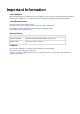
Welcome Health and Safety Information Note - The Check Point Check Point 21400 VSX correlate with the following model numbers for certification purposes: G50. Read the following warnings before setting up or using the appliance. Warning - Do not block air vents. A minimum 1/2-inch clearance is required. To prevent damage to any system board, it is important to handle it with care.
Welcome included in the manual in that alternative form, provided the user can reasonably be expected to have the capability to access information in that form. Product Disposal This symbol on the product or on its packaging indicates that this product must not be disposed of with your other household waste. Instead, it is your responsibility to dispose of your waste equipment by handing it over to a designated collection point for the recycling of waste electrical and electronic equipment.
Contents Important Information .............................................................................................3 Health and Safety Information ...............................................................................4 Introduction .............................................................................................................7 Welcome .............................................................................................................
Chapter 1 Introduction In This Chapter Welcome Overview of Check Point 21400 VSX VSX Overview Important Solutions Shipping Carton Contents 7 7 7 8 8 Welcome Thank you for choosing Check Point 21400 VSX. We hope that you will be satisfied with this system and our support services. Check Point products provide your business with the most up to date and secure solutions available today.
Important Solutions VSX incorporates the same patented Stateful Inspection and Application Intelligence technologies used in the Check Point Security Gateway product line. It runs on high speed platforms (known as VSX Gateways) to deliver superior performance in high-bandwidth environments. Administrators manage VSX via a Security Management server or a Multi-Domain Security Management, delivering a unified management architecture that supports enterprises and service providers.
Shipping Carton Contents Item Description Cables 2 power cords Documentation Getting Started Guide User License Agreement Introduction Page 9
Chapter 2 Mounting the Appliance in a Rack To learn how to mount the Check Point 21400 VSX in the rack, see the 21000 Appliances Rack Mounting Guide (http://supportcenter.checkpoint.com/file_download?id=12318).
Chapter 3 Configuring Check Point 21400 VSX The workflow for configuring Check Point 21400 VSX is: 1. 2. 3. 4. Mount the Check Point 21400 VSX in the rack. Connect the cables and power on. Use the First Time Wizard to configure the appliance. Configure VSX in SmartDashboard and install a policy. Note - Check Point 21400 VSX must be managed by a Security Management Server or Multi-Domain Security Management as described in the VSX NGX R67 Administration Guide (http://supportcontent.checkpoint.
Initial Configuration Initial Configuration Logging in for the First Time Check Point 21400 VSX includes a First Time Wizard to help you configure the initial settings for the appliance. To log in and start the First Time Wizard: 1. Connect to the appliance’s Serial console using the RJ45/D subminiature cable. 2. Connect the serial cable, RJ45/D subminiature, to the serial console port on the appliance. 3.
Initial Configuration The Network Connections window opens. 2. Enter 2. The Configure connection window opens. 3. Enter the number to select the Mgmt interface. The Choose Mgmt item to configure window opens. 4. Enter 1. The Change IP settings window opens. 5. Enter an IP address, network mask, and broadcast address for the Management interface. 6. Enter e twice to return to the Network Configuration window. 7. Enter 5. The Routing window opens. 8. Enter 1. The Set Default Gateway window opens. 9.
Confirming the Build Numbers 2. Configure the Per Virtual System State. This feature is required for the Virtual System Load Sharing (VSLS). Enter y when prompted to enable this feature. If you do not intend to use these features, enter n. Note - You can use the cpconfig CLI command to change the VSX clustering settings. Completing the Configuration Complete the last steps of the First Time Wizard. The appliance reboots and is configured according to your settings.
Chapter 4 Check Point 21400 VSX Front and Rear Panel This chapter describes the Check Point 21400 VSX front and rear panel In This Chapter Check Point 21400 VSX Front Panel Check Point 21400 VSX Rear Panel 15 19 Check Point 21400 VSX Front Panel Item Description 1 System LEDs (System power, system status, and hard disk activity). 2 LCD display screen. 3 Keypad for LCD screen. 4 2 Hard disk drives.
Check Point 21400 VSX Front Panel Item Description 9 Management connection port - for an Ethernet connection to a remote management computer. 10 USB ports. Check Point 21400 VSX Front Panel LEDS Item Description 1 System Power. 2 3 4 5 6 7 OFF - System power off ON (Green) - System power on System Status. Green – System OK Orange – Alarm for voltage, temperature or fan. Hard disk drive (HDD) Activity.
Check Point 21400 VSX Front Panel Managing Check Point 21400 VSX Using the LCD Panel The appliance has an LCD panel that you can use to do basic management operations. You can enable DHCP. You can configure the management IP address, netmask, and default gateway of the appliance. You can reboot the appliance.
Check Point 21400 VSX Front Panel Line Cards The Check Point 21400 VSX front panel has three slots for cold-swappable Line Cards (also known as Network interface Cards (NICs)).
Check Point 21400 VSX Rear Panel Item Description 5 Link 6 OFF - No Link ON (Green) - Link Link OFF - No Link ON (Green) - 10Mbps or 1Gbps Link ON (Amber) - 100Mbps Link Check Point 21400 VSX Rear Panel Item Description 1 2 redundant, hot-swappable AC power supplies. Each power supply connects to an electric outlet. 2 LED indicator for power supply, one for each power supply: OFF — power off ON (Green) — power on. 3 Main power switch.
Chapter 5 Customer Replaceable Parts For maximum availability and easy maintenance, the appliance has many customer replaceable parts. Important - customers are prohibited by warranty and support agreements from changing any parts or altering the hardware in any way except as noted below, or as directed by Check Point technical support.
Installing and Removing Transceivers To install a Line Card: 1. Turn off the appliance 2. Insert the Line Card with the ejectors rotated out a small distance. Make sure that the alignment pins behind the thumb screws engage the top hole. 3. Push the card in until the Line Card is fully inserted. When the card is fully inserted, the ejector rotates in. 4. Tighten the thumb screws on the two sides of the Line Card. Installing and Removing Transceivers Line Cards with fiber optic ports require transceivers.
Installing and Removing Power Supplies CLASS 1 LASER PRODUCT. A TOTALLY ENCLOSED LASER SYSTEM CONTAINING A CLASS 1 LASER. Note - Laser radiation when open. Do not stare into the beam, do not view directly with optical instruments, and avoid direct exposure to the beam. To install a transceiver: 1. Push the transceiver into an available port in the Line Card. 2. Turn the transceiver latch lever down to secure the transceiver in the Line Card. 3. Insert a correct interface cable into the transceiver.
Installing and Removing Hard Disks The power supply LEDs at the rear of the appliance show the status of the power supplies. To remove a power supply unit: 1. Loosen the retaining screw located at the top left of the power supply. 2. Unlock the power cord clip. 3. Pull the extraction handle to remove the power supply unit. Note - Use only the extraction handle to remove the power supply unit.
Installing and Removing Hard Disks To remove a hard disk 1. Move out the LCD panel and lock the spring-loaded screw into retaining ring. 2. On the hard disk drive, push left on the ejector handle and turn outward. 3. Remove the hard disk drive by pulling on the ejector handle and the hard disk drive bezel. Move the hard disk drive of the chassis. To install a hard disk: 1. Insert the hard disk drive into the slot. 2. Turn the ejector handle to the closed position. 3.
Installing and Removing Memory The mirror rebuild is automatic. The two disks must be the same type. First Boot Up At first boot up, let the disk fully synchronize. After two hours, the disks are synchronized. Do not reboot the system until the disks are fully synchronized. If you reboot before the disks are synchronized, the synchronization starts again at the next boot. To monitor the RAID state of the disks from the CLI 1. Log in to the appliance 2. Enter expert mode 3.
Installing and Removing Memory Caution- To protect the appliance and the memory modules from electrostatic discharge damage, make sure you are properly grounded before you touch these components. Use a grounding wrist strap and follow the instructions provided with the wrist strap before you handle the components or open the appliance. The grounding plug on the rear of the appliance ("Check Point 21400 VSX Rear Panel" on page 19) provides a chassis grounding point.
Installing and Removing Memory When performing a memory upgrade to the basic memory configuration: Install more DIMMS in all the remaining slots. The DIMMs slots must always be populated as shown in the diagram. 3. To remove a DIMM: a) Press the two retaining clips outward b) Carefully pull the DIMM up. You will possibly find it necessary to pull one end of the DIMM and then the other to gradually release it from the contact pins. 4.
Installing and Removing Cooling Fans Installing and Removing Cooling Fans The 5 CPU fan units are hot swappable. You can remove and install a fan unit at the rear of the appliance without shutting down the appliance. Before You Start: To replace a fan unit, you need: Physical access to the appliance Replacement fan unit Flat headed screwdriver Caution - Components inside the appliance can overheat if they are not cooled even for a short period of time.
Installing and Removing the System Board Battery 4. Pull the fan out to remove it. If necessary, use leverage. For example, use the flat head of a screwdriver to slowly remove the fan unit, because of the tight fit. 5. If the appliance is running, immediately install a replacement fan. Push the fan into the chassis until it locks into position. 6. Replace the fan grille. 7. Tighten the retaining thumb screw of the fan grille.
Installing and Removing a LOM Card d) Loosen the two retaining screws for the lower tray ("Check Point 21400 VSX Rear Panel" on page 19). e) Pull hard on the extraction handles, and fully remove the tray from the appliance. 2. Find the small coin battery. It is in a black battery slot on the left wall of the system board tray, looking from the rear. 3. Remove the battery: a) Move aside the battery retaining clip.
Installing and Removing a LOM Card a) Move the system board tray into the appliance until it clicks into position. b) Refasten the two retaining screws for the lower tray. c) Connect the power cords to the appliance. d) Press the power switch at the rear of the appliance, to turn on the power to the appliance.
Chapter 6 VSX Appliance Recovery VSX comes preloaded on your Check Point 21400 VSX appliance. If, for any reason, you need to reinstall VSX on the appliance, follow this procedure. To reinstall VSX software on the appliance: 1. Connect to the appliance console using the designated cord received in your shipping carton (RJ45/Dsubminiature cable) and connect to the console using Terminal Emulation software, such as HyperTerminal or PuTTY. 2.
Chapter 7 Registration and Support In This Chapter Registration Support Where To From Here? 33 33 33 Registration Check Point 21400 VSX requires a specific Check Point license. Obtain a license and register at the Check Point Appliance Registration site (http://register.checkpoint.com/cpapp). Note - The MAC address of the management interface is required to obtain a license.
Appendix A Compliance Information This appendix contains declaration of conformity, compliance, and related regulatory information. In This Appendix Declaration of Conformity 34 Declaration of Conformity Manufacturer’s Name: Check Point Software Technologies Ltd.
Declaration of Conformity Safety EN 55024 Information Technology Equipment - Immunity Characteristics EN61000-4-2 Information Technology Equipment - Electrostatic Discharge Immunity EN61000-4-3 Information Technology Equipment - Radiated RF Immunity EN61000-4-4 Information Technology Equipment - Fast Transient Immunity EN61000-4-5 Information Technology Equipment - Surge Immunity EN61000-4-6 Information Technology Equipment - Conducted RF Immunity EN61000-4-11 Information Technology Equipment