Force Test Stand Model ESM301 / ESM301L Version 2 U se r’s Guide
Model ESM301 / ESM301L Version 2 Test Stand User’s Guide Thank you… Thank you for purchasing a Mark-10 ESM301 / ESM301L Version 2 Force Test Stand, designed for producing up to 300 lbF (1.5 kN) of tension or compression force. The ESM301 is an essential component of a force testing system, typically also comprising a force gauge and grips. With proper usage, we are confident that you will get many years of great service with this product.
Model ESM301 / ESM301L Version 2 Test Stand User’s Guide 1 OVERVIEW 1.1 List of included items Qty.
Model ESM301 / ESM301L Version 2 Test Stand User’s Guide 2 MECHANICAL SETUP AND SAFETY 2.1 Safety / Proper Usage Typical materials able to be tested by the ESM301 include many manufactured items, such as springs, electronic components, fasteners, caps, films, mechanical assemblies, and many others.
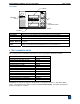
Model ESM301 / ESM301L Version 2 Test Stand User’s Guide 2.2 Setting up the Controller The power plug and controller cable must be connected to the rear of the controller, as shown in the illustration below: 1 2 3 4 5 6 1. Fuse 2. Controller Cable Connector Plug one end of the cable into this connector, and the other end into the connector as shown in the illustration on the right. 3. PC Output Connector Outputs force only or force and travel data via RS-232.
Model ESM301 / ESM301L Version 2 Test Stand User’s Guide at all times. 3. Make sure the electrical outlet powering the test stand has local earth ground (3-prong connector). 4. The test stand should be serviced by a trained technician only. Power must be disconnected before the controller is opened. After the above safety checks and procedures have been performed, the test stand may be powered on and is ready for operation. 3 OPERATION BASICS 3.
Model ESM301 / ESM301L Version 2 Test Stand User’s Guide 3.2 Controls DISPLAY EMERGENCY STOP UP STOP / ZERO TRAVEL DISPLAY DOWN SOFT KEYS Key SOFT KEYS UP DOWN STOP / ZERO TRAVEL DISPLAY EMERGENCY STOP Primary Function Functions are determined by the corresponding text on the display. Commences movement in the up direction. Commences movement in the down direction. Stops crosshead movement / zeroes travel display (if travel indication is enabled).
Model ESM301 / ESM301L Version 2 Test Stand S PEED : User’s Guide 10 . 00 ESC <− −> Label ESC <– – > ENTR Description Exits Test Parameter Setup, reverts to Operating Mode Scrolls to the previous parameter Scrolls to the next parameter Selects the parameter, allowing it to be modified ENTR When the parameters have been configured as desired and are ready to be saved, press ESC to exit Test Parameter Setup.
Model ESM301 / ESM301L Version 2 Test Stand User’s Guide 4.1 Speed, Up Speed, Down Speed (SPEED, UP SPEED, DOWN SP) If the independent up and down speed option has not been enabled, the up and down speeds will be the same, and is programmed in the SPEED parameter. If independent up and down speeds are enabled, UP SPEED and DN SPEED parameters will be present, and may be set individually. Default setting: 10 in/min Available settings: 0.02 – 45 in/min UP SPEED : ESC Label − 10 .
Model ESM301 / ESM301L Version 2 Test Stand User’s Guide 4.3 Cycling (CYCLES) This setting allows the user to configure the number of up and down cycles through which the crosshead will sequence. One cycle consists of the crosshead moving to a limit switch or soft limit, whichever occurs first, at the specified speed, stopping for the specified amount of dwell time, and returning to the other limit at the specified speed.
Model ESM301 / ESM301L Version 2 Test Stand User’s Guide 4.5 Upper and Lower Travel Limits (UPPER LM and LOWER LM) This setting corresponds to the travel distance the crosshead moves before stopping or cycling. Upper and lower limits are programmed individually. The programmed distances are relative to the zero position of the crosshead. The travel indicator can be zeroed by pressing and holding STOP for 3 seconds. Default settings: +12.000 in, -12.000 in Available settings: From -19.000 to +19.
Model ESM301 / ESM301L Version 2 Test Stand User’s Guide 4.7.1 Preload (PRELOAD) This setting corresponds to the test stand’s response to an initial load, referred to as a preload. The crosshead can stop and/or zero the travel display when the preload has been reached. This function is useful for applications such as spring testing, elongation testing, and tensile and compression testing of various materials. For details about setting the preload value, refer to Section 4.7.2.
Model ESM301 / ESM301L Version 2 Test Stand L OA D HO L D I NG : ESC Label + or – ENTR ESC − + User’s Guide ON ENTR Description Cycles through the available settings Returns to the Test Parameter Setup menu Exits the parameter without saving changes 4.9.1 Break Detection This setting directs the test stand to stop when a sample break has occurred. The test stand is triggered when the force has decreased to a specified percentage of peak.
Model ESM301 / ESM301L Version 2 Test Stand User’s Guide Default setting: CONSOLE Available settings: CONSOLE, PC CON T RO L : ESC Label + or – ENTR ESC − CON S O L E + ENTR Description Cycles through the available settings Returns to the Test Parameter Setup menu Exits the parameter without saving changes 4.11 Baud Rate (BAUD RATE) This setting corresponds to the baud rate setting of the computer program controlling the test stand.
Model ESM301 / ESM301L Version 2 Test Stand UN I T S : ESC Label + or – ENTR ESC User’s Guide i n / mi n − + ENTR Description Cycles through the available settings Returns to the Test Parameter Setup menu Exits the parameter without saving changes 4.14 Programmable Button Function (KEYS) Three button function modes are available: 1. Maintained The crosshead will move continuously once the button has been pressed and held.
Model ESM301 / ESM301L Version 2 Test Stand UNITS: KEYS: PASSWORD: User’s Guide in/min maintained 0000 (off) Default setting: off Available settings: off, on D E F AUL T ? : ESC Label + or – ENTR ESC − NO + ENTR Description Cycles through the available settings Returns to the Test Parameter Setup menu Exits the parameter without saving changes 4.16 Password (NEW PWORD) If desired, a password can be set to prevent unwanted changes to test parameters.
Model ESM301 / ESM301L Version 2 Test Stand User’s Guide 5. Load Holding Mode Crosshead moves to a force set point, stops, then dynamically adjusts position to maintain the programmed force. An auto-return or cycle/dwell time sequence may follow. 6. Break Detection Crosshead stops when a sample break has been detected. An auto-return or cycle/dwell time sequence may follow. 7. PC Mode Test stand is controlled through a serial connection with a PC.
Model ESM301 / ESM301L Version 2 Test Stand User’s Guide 3. Cycling Mode (travel indication not enabled): CYCLES REMAINING TRAVEL CYCL ES : 00024 me n u m i n ma x SET Note: The min and max keys will not appear when a password has been set. 4. PC Mode Appears the same as in Basic and Auto Return modes. Label menu min max set Description Enters Test Parameter Setup Sets speed to minimum speed. Will not appear when a password has been set. Sets speed to maximum speed.
Model ESM301 / ESM301L Version 2 Test Stand User’s Guide button counter-clockwise until it assumes its original position. To resume the test, press UP or DOWN. Crosshead movement will take place until a limit has been reached. If the crosshead has stopped at a soft limit, the limit condition may be overridden by pressing and holding UP or DOWN. 5.3.1 Travel Indication If enabled, travel indication is displayed in the upper left corner of the display.
Model ESM301 / ESM301L Version 2 Test Stand User’s Guide 3. Crosshead reverses direction, returns to the other limit at the specified speed, and stops for the specified amount of dwell time. A cycling sequence can be initiated from any position and can start in either direction. If the crosshead is at a limit, however, cycling can only be started in the direction of the other limit. To initiate a cycle sequence, press UP or DOWN.
Model ESM301 / ESM301L Version 2 Test Stand User’s Guide lower limit switch. Note 2: Preload and Load Holding cannot be enabled simultaneously. 5.6 Load Holding Mode In this mode, the crosshead moves until the set point value programmed in the force gauge is reached. The crosshead then dynamically adjusts its position to maintain a programmed force. The force gauge’s capacity should be as close as possible to the intended load, for best performance. In the force gauge, both set points must be set.
Model ESM301 / ESM301L Version 2 Test Stand d e f g h i j k l m n o p q r s t u v w x z User’s Guide Move crosshead down Set speed (ex. e10.00 = 10.00 in/min) Set cycles (ex. f0500 = 500 cycles) Set lower travel limit (ex. g05.375 = 5.375 in) Set upper travel limit (ex. h10.250 = 10.
Model ESM301 / ESM301L Version 2 Test Stand User’s Guide 6 COMMUNICATING WITH MESURTMGAUGE The ESM301 can communicate with MESURTMgauge data collection software. The test stand can output either force data only or force data combined with travel data (if the ESM301(L)-001 integrated travel indication option is installed). To communicate with MESURTMgauge, certain settings in the test stand and force gauge are required, as follows: 1. Check physical connections (refer to Section 3.4) 2.
Model ESM301 / ESM301L Version 2 Test Stand User’s Guide An example is shown below: KEYS : E SC 0139027 + − ENTR The request code must be supplied to Mark-10 or a distributor, who will then provide a corresponding authorization code to activate the feature. The process for entering the authorization code is as follows: 1. The first digit of the request code will be flashing. Press + to increment the digit. Pressing + when the number 9 is displayed will return to 0. 2.
Model ESM301 / ESM301L Version 2 Test Stand User’s Guide To clear any of the above errors, press STOP. The amber light in the STOP button will be blinking when the error message is displayed. 2. The crosshead will move only in one direction, or not at all. Possible causes: 1. Ensure all cables are plugged in properly, as described in Section 2.2. 2. Ensure that the force value has not exceeded the overload limits configured in the gauge. 3. Ensure that force gauge set points have been configured properly.
Model ESM301 / ESM301L Version 2 Test Stand User’s Guide subcomponents of the test stand (ex. fasteners, brackets, etc). All components should be firmly attached. If any looseness is detected, stop using the test stand and contact Mark-10 or a distributor for instructions. 10 SPECIFICATIONS Load capacity: 300 lbF [1.5 kN] @ up to 24 in/min [610 mm/min] 200 lbF [1 kN] @ >24 in/min [>610 mm/min] 0.5-13 in/min [13-330 mm/min] ESM301: 11.5 in [292 mm] ESM301L: 18.0 in [457 mm] ±0.
Model ESM301 / ESM301L Version 2 Test Stand User’s Guide NOTES: 27