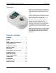
Series TT02 TORQUE TOOL TESTERS User’s Guide
Series TT02 Digital Torque Tool Testers User’s Guide Thank you… Thank you for purchasing a Mark-10 Series TT02 digital torque tool tester, designed to measure the torque produced by manual and electric torque tools. With proper usage, we are confident that you will get many years of great service with this product. Mark-10 instruments are ruggedly built for both laboratory and industrial environments. This User’s Guide provides setup, safety, and operation instructions.
Series TT02 Digital Torque Tool Testers User’s Guide 1 OVERVIEW 1.1 List of included items Qty. 1 1 1 1 1 Part No.
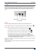
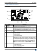
Series TT02 Digital Torque Tool Testers User’s Guide 2 POWER The TT02 is powered either by an 8.4V NiMH rechargeable battery or by an AC adapter. Since these batteries are subject to self discharge, it may be necessary to recharge the unit after a prolonged period of storage. Plug the accompanying charger into the AC outlet and insert the charger plug into the receptacle on the tester (refer to the illustration below). The battery will fully charge in approximately 8 hours.
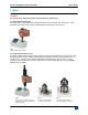
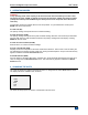
Series TT02 Digital Torque Tool Testers User’s Guide 3 SETUP Caution! Do not use Series TT02 torque testers with pneumatic or impact tools. 3.1 Using manual torque tools Use a bit adapter of appropriate size and place the tool into the receptacle, as shown in Fig. 1 below. Gradually exert torque by hand until the desired status is achieved (ex. click, slip, etc.). Fig. 1 Typical manual torque tool test 3.
Series TT02 Digital Torque Tool Testers User’s Guide 3.3 Proper alignment Align the tool axially with respect to the square drive in the receptacle. Side loading or off-center loading may produce erroneous readings, and can damage the instrument. Note: It is normal to detect a small amount of mechanical play in the receptacle. 3.
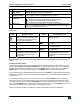
Series TT02 Digital Torque Tool Testers User’s Guide 4 HOME SCREEN AND CONTROLS 4.1 Home Screen 1 2A 10 2B 3 9 4 8 7 No. 1 2A, 2B Name Measurement direction indicator Peaks 3 Primary reading 4 Units 5 Load bar 6 Mode 6 5 Description – indicates clockwise direction – indicates counter-clockwise direction These indicators are used throughout the display and menu. The maximum measured clockwise and counter-clockwise readings.
Series TT02 Digital Torque Tool Testers 7 Number of stored data points Battery / AC adapter indicator High / low limit indicators 8 9 10 Set points User’s Guide See Operating Modes section for details about each of these modes The number of stored data points in memory, up to 1,000. Displayed only if Memory Storage is enabled for the DATA key. Either the AC adapter icon or battery power icon will be shown, depending on power conditions. Refer to the Power section for details.
Series TT02 Digital Torque Tool Testers User’s Guide 5 OPERATING MODES Caution! In any operating mode, if the capacity of the instrument has been exceeded by more than 110%, the display will show “OVER” to indicate an overload. A continuous audible tone will be sounded (if beeps are enabled) until the MENU key has been pressed or the torque has been reduced to a safe level). Five operating modes are possible with the TT02 torque tester. To cycle between the modes, press MODE while in the home screen. 5.
Series TT02 Digital Torque Tool Testers User’s Guide 7 DIGITAL FILTERS Digital filters are provided to help smooth out the readings in situations where there is mechanical interference in the work area or test sample. These filters utilize the moving average technique in which consecutive readings are pushed through a buffer and the displayed reading is the average of the buffer contents. By varying the length of the buffer, a variable smoothing effect can be achieved.
Series TT02 Digital Torque Tool Testers User’s Guide SET POINTS Upper Disabled * Upper Enabled 5.00 Lower Disabled * Lower Enabled 3.50 Either one, two, or none of the set points may be enabled. To toggle between the clockwise and counterclockwise directions, press the DIRECTION key. If two set points have been enabled, they are displayed in the upper left corner of the display. If only one set point has been enabled, the word “OFF” will appear in place of the value.
Series TT02 Digital Torque Tool Testers User’s Guide MEMORY View Data View Statistics Output Data Output Statistics Output Data & Stats Clear All Data 9.1 View Data All the saved data points may be viewed. The record number is displayed, along with the corresponding value and presently set unit of measurement. Any readings may be deleted individually. To do so, scroll to the desired reading and press DELETE.
Series TT02 Digital Torque Tool Testers User’s Guide Note: Data is not retained while the tester is powered off. However, the tester protects against accidental or automatic power-off.
Series TT02 Digital Torque Tool Testers User’s Guide 10.2.2 Data Format Select the desired data format. The screen appears as follows: * DATA FORMAT Numeric + Units Numeric Only Invert Polarity Omit Polarity Selection Numeric + Units Numeric Only Invert Polarity Omit Polarity Description Output format includes the value and unit of measure. Clockwise values have positive polarity, counter-clockwise values have negative polarity. Output format includes the value only. Polarity same as above.
Series TT02 Digital Torque Tool Testers User’s Guide 10.5 DATA Key Settings To configure the functions of the DATA key, select DATA Key from the menu.
Series TT02 Digital Torque Tool Testers Torque CW torque greater than lower set point CW torque greater than upper set point CCW torque greater than lower set point CCW torque greater than upper set point Both set points are CW User’s Guide Pin function Both set points CW upper set point, are CCW CCW lower set point CCW upper set point, CW lower set point N/A Pin 11 active N/A Pin 11 active Pin 11 active N/A Pin 12 active N/A Pin 12 active N/A Pin 11 active N/A N/A Pin 12 active N/A Pin
Series TT02 Digital Torque Tool Testers User’s Guide 11.2 Settings Set up the trigger for auto output and storage, and the delay to zero the primary and peak readings. The display will appear as follows: BREAK DETECTION SETTINGS Trig. Threshold 5 % Auto Zero Delay 3 sec. Trig. Threshold Auto Zero Delay Sets the percentage of full scale at which the break detection feature becomes active. This threshold is provided to ignore peaks that can occur during sample loading and unloading.
Series TT02 Digital Torque Tool Testers User’s Guide FIRST/SECOND PEAK * Enabled + Peak Settings + Auto Output * Auto Store PK1 Auto Store PK2 * Auto Zero Any combination of the above functions may be selected. Function Enabled Peak Settings Auto Output Auto Store PK1 Auto Store PK2 Auto Zero Description If enabled, 2PK will appear as one of the operating modes. In the main display, the Peak readings will reference the first and second peaks – first peak on top, second peak below.
Series TT02 Digital Torque Tool Testers User’s Guide 11.3 Auto Output Settings Select the output type. Select RS-232/USB and/or Mitutoyo outputs, and select First and/or Second peaks. The display will appear as follows: AUTO OUTPUT SETTINGS RS232/USB Output Mitutoyo Output First Peak Second Peak 13 CALIBRATION 13.1 Initial Physical Setup The TT02 should be mounted to a fixture rugged enough to withstand a torque equal to the full capacity of the instrument.
Series TT02 Digital Torque Tool Testers User’s Guide example, Model MTT02-50 (with capacity of 50 lbFin) should be calibrated at 10, 20, 30, 40, and 50 lbFin loads in each direction. 2. To escape the Calibration menu at any time, press ESCAPE. The display will appear as follows: CALIBRATION NOT COMPLETE CANCEL EXIT W/O SAVING Selecting “CANCEL” will revert back to the Calibration setup. Selecting “EXIT W/O SAVING” will return to the menu without saving changes. 3.
Series TT02 Digital Torque Tool Testers User’s Guide Attach weight fixtures (brackets, cable, hook, etc), as required. Do not yet attach any weights or apply any calibration loads. Then press ENTER. 6. The display will appear as follows: CALIBRATION CLOCKWISE Optionally exercise load cell a few times. THEN PRESS ENTER Optionally exercise the internal sensor several times (at full scale, if possible), then press ENTER. 7.
Series TT02 Digital Torque Tool Testers User’s Guide 10. After all the clockwise calibration points have been completed, the display will appear as follows: CALIBRATION CLOCKWISE COMPLETE REVERSE DIRECTION FOR CCW Attach necessary weight fixtures. THEN PRESS ENTER Press ENTER. 11. At the completion of the counter-clockwise calibration, the display will appear as follows: CALIBRATION COMPLETE SAVE & EXIT EXIT W/O SAVING To save the calibration information, select “SAVE & EXIT”.
Series TT02 Digital Torque Tool Testers User’s Guide CALIBRATION COUNTER-CLOCKWISE LOAD TOO CLOSE TO PREVIOUS PLEASE TRY AGAIN The entered calibration point is too close to the previous point. 14 PASSWORDS Two separate passwords may be set to control access to the Calibration section and to the menu and other keys. To access the passwords setup screen, select Passwords from the menu. The display will appear as follows: PASSWORDS Calibration Menu Key Mode Key Zero Key Data Key 14.
Series TT02 Digital Torque Tool Testers User’s Guide ENTER PASSWORD (0000 – 9999) 5000 Use the UP and DOWN keys to select the correct password, then press ENTER to continue. If the incorrect password has been entered, the display will appear as follows: INCORRECT PASSWORD Reset password Request code: XXXX Press ENTER or ESC To re-enter the password, press ESC to exit to the home screen. Then, access the desired function and enter the password again when prompted.
Series TT02 Digital Torque Tool Testers User’s Guide BACKLIGHT Off On * Auto Set Minutes 1 Select Off for the backlight to be off upon powering on the tester. Select On for the backlight to be on upon powering on the tester. Select Auto for the backlight to be on upon powering on the tester, but will shut off after a period of inactivity (as defined in the Automatic Shutoff sub-section). The backlight will turn on again when activity resumes.
Series TT02 Digital Torque Tool Testers User’s Guide INITIAL SETTINGS Units lbFin Mode Real Time For available units, refer to the Units section. For available modes, refer to the Home Screen And Controls section. 15.6 Information / Welcome Screen The following screen is displayed at power-up and can be accessed at any time by selecting Information from the menu: Digital Torque Tester Series TT02 Model No: MTT02-50 Serial No: 1234567 Version: 1.0 (c) Mark-10 Corp. 16 SPECIFICATIONS 16.
Series TT02 Digital Torque Tool Testers User’s Guide 16.
Series TT02 Digital Torque Tool Testers User’s Guide 16.3 Capacity x Resolution Model No. MTT02-12 MTT02-50 MTT02-100 ozFin 192 x 0.1 800 x 0.5 1600 x 1 lbFin 12 x 0.005 50 x 0.02 100 x 0.05 lbFft 1 x 0.0005 4 x 0.002 8 x 0.005 Ncm 135 x 0.1 570 x 0.5 1150 x 0.5 Nm 1.35 x 0.001 5.7 x 0.005 11.5 x 0.005 16.