
Product Manual


User Manual
Page 11
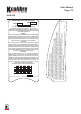
FABX2R Self-Retracting Lifeline
US Patent No. 8,991,556
European Patent No. 2185247 & 2495017
J F M AA JM J S O N D
YR
YR
YR
YR
YR
Lot #:
32130
Part #:
91064 (Rev. A)
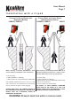
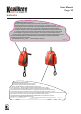
FABX2R SRL & Emergency Rescue
This unit is designed to be used as a fall arrest block and a retrieval device in
emergency situations to rescue after a fall - rescue/recovery winch. 1 - Before use ensure the
security tag and pin are present and intact. If missing or damaged DO NOT USE. 2. The device should be
mounted in a bracket to a tripod or davit. 3 - Ensure there is sufficient free area around the FABXR for
the handle to fully rotate. If the user falls the FABXR brakes will automatically lock and arrest the fall safely.
4 - To engage the main drive first remove the security tag and pin. Next push the small knob to release handle
from housing and to engage retrieval gears into position. 5 - To raise a person, rotate the handle clockwise.
6 - To lower a person, rotate the handle clockwise 1/8th of a turn to release the brakes, then rotate counter-clockwise
DO NOT USE RECOVERY HANDLE TO CARRY THE FABXR. DO NOT ALLOW LINE TO GO SLACK IN RESCUE MODE.
If in doubt see user manual for clarification.
MAX USER WEIGHT : 141kg /310lbs MAX LIFT DISTANCE: 15m/50ft
91064 (Rev. A)
91064 (Rev. A)
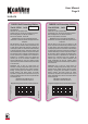
SPECIFICATIONS:
Lifeline: 50’ x 3/16” Stainless Steel
Capacity range: 130 - 310 lbs. Avg. arresting force: 900 lbs.
Max. arresting distance: 54” Min. Fall clearance: 9’
Free Fall is not permitted - Class B SRL
WARNING: Prior to use, fully read and understand all
manufacturer’s instructions provided with equipment at time
of shipment.
USE: This device is only for use by one person as a fall
arrester. Only make connections directly to attachment point
on safety harness. Ensure that connection to anchorage is
secured properly before use. Avoid lifeline contact with sharp
or abrasive edges and surfaces, and thermal, electrical, and
chemical hazards. May be used as a component of a PFAS in
HLL applications. Design, installation, and utilization of HLLs
must be supervised by a Qualified Person. Unsuitable for
horizontal use. Competent Person must calculate fall
clearance prior to use; fall clearance calculations must
include considerations for swing fall. Clearance number
specified is based on lifeline installed vertically overhead and
in-line with worker.
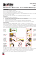
INSPECTION: Prior to each use, inspect device per
instructions, including locking function (sharp pull to test),
retraction function, legibility of labels, evidence of defects,
damage, or missing parts, and condition of connectors,
housing, fasteners, and lifeline (inspect full length).
Inspection by Competent Person required at least every 12
months. Immediately remove from service if impact indicator
on hook displays red.
ANSI Z359.14-14 & ANSI A10.32-12
OSHA 1910 & OSHA 1926 Subpart M
Designed and engineered in the UK, assembled in America.
CHECKMATE
All Intellectual Property, including drawings, branding, logo's and patents are owned by Checkmate Limited.
1:1
sales@checkmateuk.com
+44(0) 1795 668 280
+44(0) 1795 580 333
New Road, Sheerness, Kent, England ME12 1PZ, UK
www.checkmateuk.com
LET'S INNOVATE
CHECKMATE LIFTING & SAFETY
LTD
LIFTING & SAFETY
1
N/A
FABXLR Back Label
PPELAB-435
FABXLR Self-Retracting Lifeline
Lifeline: 100’ x 3/16" Stainless Steel
Capacity range: 130-310lbs. (user, tools and equipment).
Arrest distance (without free-fall). Less than 54
". Max. Arrest Force
1800lbs or less. Average arrest force: 900lbs or less. Meets or exceeds the
requirements of OSHA 1926 Subpart M, OSHA 1910, ANSI Z359.14-2014
Class B & ANSI A10.32-2012
N/A
N/A
91066 (Rev. A)
US Patent No. 8,991,556 European Patent No. 2185247 & 2495017
AC
12/03/19
1
PPELAB-435
Background Colour
Grey
Text Colour
Black
Label size
160mmx77mm
Grey
C: 0%
M: 0%
Y: 0%
K: 33%
Black-
C: 57
M: 68
Y: 67
K: 90
Red-
C: 0
M: 100
Y: 97
K: 0
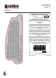
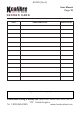
J F M AA JM J S O N D
YR
YR
YR
YR
YR
Date of First Use
WARNINGS
Read, understand & follow all manufacturer's instructions before installing
& using this product. Failure to do so may result in serious injury or death.
Device must be inspected before each and every use. Avoid lanyard contact
with sharp edges and abrasive surfaces. Do not use if this unit has been
subjected to arrest forces - Remove from service immediately.
INSPECTION
User must inspect before each use. Consult instructions for complete
inspection criteria. Ensure deployment indicator has not been deployed by
checking for a red band visible between the swivel and body of hook. If
deployed, DO NOT USE. Ensure proper locking function by pulling out 2 feet
of line, & giving it a hard tug. Ensure line & housing are free of any visible
signs of damage. Ensure lifeline pays-out & retracts smoothly. Must be
inspected by a competent person at least annually.
INSTALLATION
Follow the instruction manual & use only anchorages specified by a
qualified engineer or competent person. The anchor point must be rated to
support a 5000lbs static load. Use only locking type connectors for
connection to anchor point. Must be installed overhead, freefall is NOT
permitted. DO NOT WORK ABOVE THE ANCHORAGE. Not suitable for use
horizontally. Suitable for use with horizontal lifeline. Ensure there is
sufficient clear-fall distance. Minimum clear-fall distance: 8’ Ensure
tension is kept on the lifeline when retracting.
Designed and engineered in the UK, assembled in America.
Lot #:
32132S
Part #:
Labels