
Installation Instructions


1) Check that the connection socket of power cable, connection cable is not loose, and make sure it is connected correctly and securely.
2) Check that the neutral line and the live line of the power supply not be mixed.
3) Check if the fuse is burnt out and replace the power supply if it is damaged
4) Check that the antenna is placed in a dry, well-ventilated area to avoid board hardware failure due to moisture or water ingress.
4. Connections and Installation
1) 9PIN cable connects main board and slave board, take the color as reference.
2) 5PIN cable connects to power socket of master board.
3) After connecting the cables, power on the system. The system alarms and starts.
Can be fix installation under normal work
1) Open the base cover use Electric or manual screwdriver
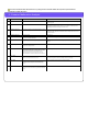
2) Antenna base mounting hole (base size): As shown in the picture below, the hole at the four corners of the base is the fixed mounting hole of the device.
3) Drill in the ground use Electric drill
4) Use the expansion screws to fix the antenna base mounting hole , the specifications of screws are M10*80mm:
5) Use the tools Wrench to screw and hammer to fix the screws.
6) Cutting the slot in the ground with an Angel Grinder , put the connection cable underground, use an stainless steel pipe to cover the cable.
7) Test he detection and finish the installation.
5. LED Indicators
1) Under normal work: a. b. c.
a. The first one on the left side of the upper row is the work indicator, which flashes slowly during normal operation;
b. The two lights on the right side of the upper row are channel indicators. The right light is on for channel 1, the left light is on for channel 2, and both the two
lights are on for channel 3. In normal operation, the system alternately displays the signal interference strength of the three channels.
c. The channel noise and environment signal is shown from the down row (the right to the left indicates the stronger of the interference signal). 1-2.5 lights on
means the interference is okay; 3 lights on means quite much interference, shorter the installation distance and adjust the system sensitivity is considered in this
situation.
2) Under abnormal operation: a. b.
a. The second one on the left side of the upper row is the fault indicator light (red light). When this light is on, it indicates that there is a fault in the operation of the
board (Factory reset can be done to solve, see factory reset function).
b. The four indicators in the lower row are all on, means too much interference or the channel signal is too weak (the lights flashes more than 3), and the system
not working. On-site environment checking and tuning is necessary in this situation (see software debugging) and then fixed installation.