
User`s guide

©Microcontroller-café & Checkpoint LAB M35160 ERASER/PROGRAMMER User’s Guide
5
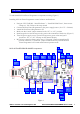
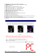
1 - Serial port: DE-9 (DB-9) connector (RS-232 standard)
2 - LED indicator: double digits (two single sections) numeric display
3 - Beeper: piezo buzzer
4 - Target socket: two straight PCB sockets (2.54 mm)
5 - PC: mode operation jumper. PC - personal computer mode
6 - AU: mode operation jumper: AU - autonomous operate
7 - RST: reset button for autonomous operate mode
8 - RD: READ/TEST button for autonomous operate mode
9 - Led1: control led (green color led)
10 - Power jack: DC power jack 2.1 mm
11 - WR: WRINC/ERASE button for autonomous operate mode
12 - Led2: program led (red color led)
13 - Led3: power/status led (green color led)
14 - 080: M35080 jumper. Select M35080-4; M35080-6 devices for autonomous operate mode
15 - TST: Self test mode: Select self test diagnostic mode
16 - 160: M35160 jumper. Select M3160; D160D0WQ; D80D0WQ devices for autonomous
operate mode
4. Quick start
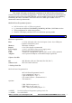
Before connecting the power plug, make sure that the power supply source is DC and
power supply voltage matches the voltage rating of the M35160 Eraser/Programmer.
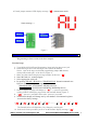
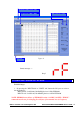
Select mode of operate Personal Computer or Autonomous by “Function” jumper:
AU mode PC mode Incorrect
Figure 2
NOTE: Personal Computer (PC) mode will active after Power On Reset only!
AU operation mode activation: mount jumper to AU position then press reset button
Left : Autonomous mode, jumper mounted into AU position
Middle : Personal Computer mode, jumper mounted into PC position
Right : Incorrect installation
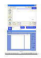
Jumper mounted to PC position, numeric display message: “ PC“ (Personal Computer)
Status message -->