
User Manual


Classic IP Style SSB Installation Manual Rev.*60
9 of 27
application developed to install and configure TR4210 boards via serial connections.
DMS provides for firmware updates without replacement of microchips.
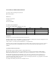
Parts
Quantity will vary according to site.
18 AWG 2-conductor (STP)
CAT5e cable
22 AWG 4-conductor (STP) (5594)
1/2” Anchor Bolts
*DekDuct (wire chase)
*Wiremold (1500 or 2600 series)
*Wiremold anchor bolts Note:
*Wire routing methods will vary by installation.
Installation Outline
Follow this sequence to successfully install the components:
1. Determine optimal antenna placement based upon antenna type, tag type, and door
opening width. (Refer to the TR4210 Product Reference Guide)
2. Determine power supply requirements and the ideal power supply location. (See
“Appendix 2 Power Supplies”)
3. Physically mount the antennas.
4. Connect the antenna wiring.
5. Install peripherals.
6. Configure the system using DMS.(Refer to test procedure P/N 7251662)
The information covered in steps 1 and 2 is generally used during the survey and planning stage,
but it is important for the installer to keep these specifications in mind to ensure that the systems
are installed to specification.