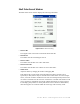
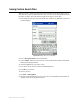
Shelf Order Search Window The Shelf Order Search window displays the following information: Figure 4.38 Shelf Order Searching • Items in file The original count of the items read from the Shelf Order file. • Items Read The number of items read during the search. • Items in order The number of items that were read in shelf order. • Items not in order The number of items that were read that are not in shelf order. • Offset in use Adjust the offset by changing the number and tapping Set.
• Alerts Enabled When checked, an alert displays and a sound occurs for items of interest. Tap this button to disable alerts. Alerts occur for the following reasons: Out of range • The item read was found in the Shelf Order list, but was not located close enough to the last item in the shelf order. Not in list • The item read was not found in the Shelf Order list. See “Shelf Order Alert” on page 4-30 for more details. 5 Tap Start to begin your inventory search.
• If Not in List, this item should probably be removed from the shelf, since it is not in the shelf order list. • If Out of Range, this item should be repositioned on the shelf in the correct order. • Show Next Displays the next item read. • Show Item Returns the display to the item that is not in the list. Tap Continue when you are ready to resume the scan. Be sure to start at the position you were in when the alert occurred.
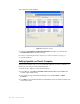
Creating a New Search List 1 Tap on the item of interest in the Shelf order results field. For example, “Items not in file.” Items in file does not generate a file. 2 Tap New Search List. 3 If a result is present, the File Created field automatically populates with the file name of the Shelf Order Search file and the correct extension “.psl”. For example, if the “Items not in file” line is selected, a new search could be performed to locate the items that do not belong on the shelf: Figure 4.
3 You may now import this file to scan for the barcode(s) into Item Search. See “Preparing an Item Search List File” on page 4-17 for more details. Viewing Shelf Order Results View List displays the results of a Shelf Order scan. Each item read is displayed in order, with the appropriate status information. Figure 4.43 Shelf Order View List window 1 Tap on the item of interest. For example, “Items in order.” The View List window appears. 2 Tap View List. 3 Tap Show Prev.
Saving Custom Search Files When you create customized search files on the Portable Data Terminal, either types of Item Searches or types of Shelf Order Searches, you can save the customized lists with a file name you input. The same directions apply for all types of search files. 1 From either the Item Search or Shelf Order main windows, tap Save As. The Save As window displays. Figure 4.44 Sample File Save As Window 2 Enter a descriptive name into the Name field.
CHAPTER ILS REMOTE MONITOR CHAPTER0 This chapter describes the ILS Remote Monitor utility and provides information on how to: • Install web site certificates on the clients (page 5-2) • Set up and manage user accounts and permissions (page 5-5) • Start up ILS Remote Monitor (page 5-8) • Single server, multi-branch environment • Peer-to-peer environment • Change branch views (page 5-9) • View the status of different branches (page 5-10) • View and print reports (page 5-11) • Upload Portable Reader inv
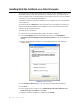
Installing Web Site Certificate on a Client Computer To establish a secure channel between the client computer and the Application Server, you must install web site certificates on both the server and the client. You must renew the server certificate yearly; you must install the client certificate only once, on each computer on which you want to use ILS Remote Monitor. Checkpoint Field Service personnel install the server certificates for you. You install the client certificates.
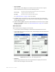
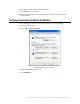
8 Click Yes to add the certificate to the Root Store. 9 Click OK to close all windows. 10 Repeat steps 1 through 8 on each client computer on which you want to use ILS Remote Monitor. Verifying Successful Certificate Installation Use the following procedure to check that the certificate is correctly installed: 1 Open a browser window. 2 Select Tools > Internet Options.... Figure 5.2 Internet Options window 3 Select the Content tab (Figure 5.2). 4 Click Publishers....
The Certificates window displays: Figure 5.3 Certificates window 5 Select the Trusted Root Certification Authorities tab (Figure 5.3). Ensure that CheckPointSystems is included in the list. 6 If not, see “Installing Web Site Certificate on a Client Computer” on page 5-2. 7 Close all windows. Setting Hyperlink on Client’s Computer This procedure indicates how to create a bookmark hyperlink on a client’s computer, so that the user can easily access ILS Remote Monitor.
Setting Up and Managing User Accounts The Remote User Manager utility lets you create and manage accounts that provide access to the ILS Remote Monitor. The utility also lets you unlock accounts that have been disabled as a result of incorrect username-password combinations. Table 5.1 lists the access privileges you can assign to each user: Table 5.1 Remote User Manager Access Privileges Access Privilege Remote Console Remote Report Description View status of any or all branches.
Figure 5.5 Remote User Manager Access Levels Select the Access Level privilege for the user (Figure 5.5). Table 5.
Removing a User Account Perform the following steps to delete an existing ILS Remote Monitor account: 1 In the Intelligent Library System Control window, select Maintenance > Remote User Manager. 2 Log on as Customer Service, user name of ils and password of maint. Figure 5.6 Remove User Account 3 Select the user name to be deleted (Figure 5.6). 4 Click Remove. 5 At the prompt, click Yes.
Using ILS Remote Monitor With the exception of starting up ILS Remote Monitor, the utility functions the same way in both single server, multi-branch and peer-to-peer environments. To start up ILS Remote Monitor, follow the instructions appropriate to your site’s environment. Launching ILS Remote Monitor in a Single Server, Multi-Branch Environment To launch ILS Remote Monitor in a single server, multi-branch environment: 1 Open a browser window.
Using ILS Remote Monitor in a Peer-to-Peer Environment ILS Remote Monitor enables you to determine the status of different servers in a peer-to-peer environment. Depending upon the URL you enter, you can different view peer servers in your network. • To view information for your own branch, enter your branch’s server name of the peer server in the browser’s address bar (example: https://rfidpeer1/ils).
Viewing Status The Status page lists the information of the currently selected Branch and all the components connected to the server. The following components’s health (status) can be monitored: • Self-Checkout Stations • Library Management System connection • Interrogators • Alarms To view the status of a branch, click on the Status tab. This is the default view. To change to a different branch, see “Changing Branch Views” on page 5-9. 5-10 ILS 2.
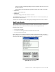
Viewing and Printing Reports Reports cannot be generated by using ILS Remote Monitor to log in to the Application Server. You can only generate reports from the Application Server, and then once generated, view those reports with ILS Remote Monitor. To view pre-run reports for a selected branch: 1 Click the Reports tab. Figure 5.9 View Reports 2 To view the report, click the desired report name (Figure 5.9). When viewing a report, you can return to the list of reports by clicking the Reports tab.
Uploading Portable Reader inventory files To upload a Portable Reader inventory file to the Application Server: 1 Click the Inventory tab. Figure 5.10 Upload Inventory 2 Enter the inventory file name, or click Browse to navigate to the inventory file (Figure 5.10). 3 Click Upload Inventory. Logging out To log out of ILS Remote Monitor: 1 Click the Logout tab. You will be logged out and have to log back in to use the utility.
CHAPTER EXCEPTION TICKET PRINTER CHAPTER0 This chapter explains the function of the exception ticket printer, and provides instructions for using the printer. This feature is optional; your site may not use the exception ticket printer.
Printer Layout Figure 6.1 and Figure 6.2 show the layout of the printer and its back panel. Printer Cover Control Panel LED Cutter Cover POWER PO WE ER R RO R PA OU PE R FE T ED ERROR PAPER OUT FEED Cover Open Button On/Off Switch Figure 6.1 Top of Printer Power Supply Connection 10/100BASE-TX FG Ethernet Connection FG DK DC24V Ground Screw Figure 6.2 Printer Back Panel 6-2 ILS 2.
Control Panel Power LED: The POWER light is on when the printer is on. Error LED: Indicates an error. Paper Out LED: On indicates a paper near end or out. Flashing indicates standby. Feed button: This button feeds paper or starts a self-test. Using the Exception Ticket Printer If the Library Management System has placed a “hold” on a particular book (or other piece of library material), the check-in of that material triggers the exception ticket printer to print a receipt.
Setting the Printer’s Cut Type Checkpoint Systems recommends that you set up the printer to do a partial cut of the paper. This produces a string of receipts, which can be easily separated, rather than individual receipts, which might fall and be lost. 1 On the computer you used to set up the printer, click Start > Settings > Printers and right-mouse click the Epson printer. 2 Select Printing Preferences. 3 Select the Paper/Quality tab. Figure 6.
Inserting Paper Take the following steps to add paper to the exception ticket printer: 1 Be sure that the printer is not receiving data. Press the Cover Open button to open the cover. 2 If present, remove any used paper roll core. Insert the paper roll in the correct direction, as shown in Figure 6.4. Cover Open PO WE ER R RO R P OUAPE R FE T ED PO WE ER R RO R P OU A PE R FE T ED Figure 6.4 Insert Paper 3 Pull out a small amount of paper, as shown in Figure 6.5.
Running a Self-Test Follow these steps to run a self-test on the paper roll: 1 Be sure that the printer is off and that the printer cover is closed properly. 2 Hold down the Feed button and turn on the printer using the switch on the front of the printer. This may take some time, so continue holding the Feed button until it prints. 3 The self-test prints the printer settings and then prints the following: If you want to continue SELF-TEST printing, Please press the PAPER FEED button.
3 Position the two hooks on the connector cover so that they hook the printer case. 4 Rotate the connector cover into the printer until it clicks into place. Attaching cover To remove the connector cover: 1 Turn the printer over, insert a flathead screwdriver under one hook, and pry up the hook while lifting the connector cover. See the illustration on the right below. 2 Repeat this step for the other side and remove the cover.
Troubleshooting The following table lists solutions to issues that might arise. Condition Solution No lights on the control panel Check the power supply cable connections and the power outlet. ERROR light on (not flashing) with no printing • If PAPER OUT is on, the paper roll is not installed or is near the end. • If PAPER OUT is off, the printer cover is not closed properly. ERROR light flashing with no printing (and no paper jam) Printing stops if the head overheats and resumes when it cools.
Cleaning the Print Head Caution After printing, the print head can be very hot. Be careful not to touch it, and to let it cool before you clean it. Do not damage the print head by touching it with your fingers or any hard object. Take the following steps to clean the print head: 1 Turn off the printer, open the paper roll cover, and clean the thermal elements of the print head with a cotton swab moistened with an alcohol solvent (ethanol, methanol, or IPA).
Notes 6-10 ILS 2.
CHAPTER CHECKVIEW CHAPTER0 This chapter describes the CheckVIEW utility and provides instructions for: • Using CheckVIEW (page 7-3) • Reinstalling missing files (page 7-6) • Uninstalling CheckVIEW (page 7-6) • Using CheckVIEW to shut down a monitored Self-Checkout Station (page 7-6) • Troubleshooting information (“CheckVIEW Troubleshooting” on page 12-9). The CheckVIEW utility enables library staff to remotely view up to four different Self-Checkout Station at one time.
The VNC server application must be installed on every Self-Checkout Station that is to be monitored by the library staff’s computer. TCP/IP network connectivity to the Self-Checkout Stations is required for monitoring Self-Checkout Stations. Self-Checkout Station running CheckVIEW Self-Checkout Station running CheckVIEW Intranet (High Speed LAN) Self-Checkout Station running CheckVIEW Computer running VNC Viewer in Monitor mode Self-Checkout Station running CheckVIEW Figure 7.
Using CheckVIEW in Monitor Mode To launch the CheckVIEW application, select Start > Programs > Checkpoint Systems > CheckVIEW Monitor from the library staff’s computer. The default main page appears in Monitor mode with up to four Self-Checkout Stations displayed. Name of Self-Checkout Monitoring mode showing three active Self-Checkout displays. This area is empty. A fourth Self-Checkout appears here when active. Figure 7.
Using CheckVIEW in Host Mode To gain access to a specific Self-Checkout Station to assist a patron: 1 Select View from the menu. 2 Select one of the Display (1-4) options. You can also press Ctrl+1-4 using your keyboard to access a Self-Checkout Station. Access to the window is shared between the staff member and the patron. The Self-Checkout Station window reacts to the most recent command by either the patron or the staff member. Assist mode.
3 To add a Self-Checkout Station so that it displays in CheckVIEW, enter 1 where it states Enabled, next to Display Index. See Figure 7.4, “Self-Checkout Station Monitoring Enabled.” Figure 7.4 Self-Checkout Station Monitoring Enabled Note: Enable only those Self-Checkout Station you are going to actively view, otherwise the monitoring system slows down. 4 To remove a Self-Checkout Station from CheckVIEW, type a 0. Figure 7.
Reinstalling Missing Files Use the Repair function to reinstall missing or corrupt files, registry keys, and shortcuts. 1 Insert the CheckVIEW CD-ROM into the computer’s CD-ROM drive. If CheckVIEW is already installed, the Application Maintenance window displays. Figure 7.6 Application Maintenance window 2 Click the Repair option button. Click Next. Uninstalling CheckVIEW Use the Remove function to uninstall CheckVIEW. 1 Insert the CheckVIEW CD-ROM into the computer’s CD-ROM drive.
4 Click Shut down. The Self-Checkout Station enters a shut down sequence until it states that Self-Checkout Station can be turned off. Power On/Off Switch Figure 7.7 Self-Checkout Station On/Off Switch 5 Go to the Self-Checkout Station and turn off the power switch. Note: See “Powering On the Self-Checkout Station” on page 3-10 for instructions about how to turn on the Self-Checkout Station.
Notes 7-8 ILS 2.
CHAPTER CIRCULATION CIRCUIT PROGRAMMER CHAPTER0 Overview The Circulation Circuit Programmer (CCP) is a combination hardware and software solution for programming Circulation Circuits and printing barcode labels. Libraries use the CCP to program circulation circuits with the item identifier from the barcode when converting a retrospective library collection. Circulation circuits are also programmed when new materials are added to the collection.
barcode label at the same time when programming a circulation circuit linking the same item identifier used by the barcode and the circulation circuit. See “Programming Circuits for RFID and Barcode Items” on page 8-5 for detailed information. The high-level process by which circuits are programmed is as follows: 1 If programming new materials, enter the new item identifier. If using barcodes, scan the barcode for the item identifier. 2 Wave the circulation circuit over the CCP.
If necessary, launch LabelView if you plan to print labels. Figure 8.1 Auto-Increment Select 2 Click File > Auto-Increment Format and select the file format specified for your library. If using only one format file, then you will only perform this step once. If you have opted to print labels, click File > Label Format and select the label designed for your library. Figure 8.2 Auto-Increment Button 3 Once configured, click the Auto-Increment button. The Auto-Increment window displays: Figure 8.
The programming window displays: Figure 8.4 Auto-Increment Programming 5 Options that can be selected by clicking its checkbox: Note: • Program Continuously: Selecting allows you to continuously program. • Display Circuit Overwrite Warnings: Select if you wish to see a warning dialog box when reprogramming a circulation circuit. This feature is useful if you selected Program Continuously so that you do not inadvertently program a circulation circuit with another item identifier.
• If you selected Program Continuously, just wave the next circulation circuit over the CCP. • If not, click Program a Circuit to program the next tag. Programming Circuits for RFID and Barcode Items This section provides instructions on how to program items (books, dvds, etc.) that use circulation circuits and barcodes. To program RFID circulation circuits using Barcodes: 1 Launch the CCP by clicking Start > All Programs > Circulation Circuit Programmer.
Program Continuously so that you do not inadvertently program a circulation circuit with another item identifier. • Print Labels: Select if you are printing a label for each circulation circuit you program. 5 Scan the barcode. The barcode number appears: Figure 8.7 Barcode Programming 6 Wave the circulation circuit over the CCP. The circulation circuit is read more quickly if you use and up and down motion over the CCP, instead of waving across the unit.
Troubleshooting Label Printing Error An error occurs when printing. If the fault light flashes and your printer does not have a built-in cutter, you need to deselect the cutter option in the label properties. 1 If the program is not activated, launch LabelView by clicking Start > All Programs > CheckPoint XLT+ 7.04 > CheckPoint XLT+ 7.04 to start the program. 2 Press Ctrl + L to access Label Setup. 3 Select the Options tab. 4 Select Don't Cut from the Cut dialog.
3 Double-click Add Printer. 4 Click Next at the initial screen. 5 Select Local printer attached to this computer. Deselect Automatically detect and install my Plug and Play printer and click Next. 6 Select LPT1: (Recommended Printer Port), if not already selected and click Next. 7 Select Have Disk.... 8 Select your CD-ROM drive and navigate to the Windows Driver folder. 9 Click Open. 10 Click OK. 11 Select the type of printer you are installing. The current printer used is the Meto mn 4203 and click Next.
CHAPTER AFFIXING CIRCULATION CIRCUITS CHAPTER0 This chapter describes the different types of Circulation Circuits (tags) and provides instructions for placing the appropriate circuit on books, CDs, audio material, and kit material. For information on the optional Circulation Circuit Programming Station, see “Circulation Circuit Programmer” on page 8-1. Types of Circulation Circuits Checkpoint Systems provides three types of Circulation Circuit. Choose the appropriate circuit for each type of media.
Video Circulation Circuit: Can be used on video cassettes. Figure 9.2 Video Circulation Circuit • CD-DVD Circulation Content Circuit: Can be used on CDs and DVDs (aka hub tag). Figure 9.3 CD-DVD Content Circulation Circuit Applying Circulation Circuits to Books Use only Standard Circulation Circuits on books. To place Circulation Circuits on books: 1 Place the Circulation Circuit on or near the back cover, horizontally one-inch (2.5 cm) from the spine and vertically centered on the page.
3 Place the cover label over the Circulation Circuit. You can print a barcode as part of the cover label. Figure 9.4 Sample Placement of Circulation Circuit and Label on a Book Applying Circulation Circuits to Video Cassettes Use only Video Circulation Circuits on video cassettes. To place Circulation Circuits on video cassettes: 1 Place the Circulation Circuit on the spine of the cassette, on the same side as the title label. 2 Place the cover label over the circulation circuit.
Applying Circulation Circuits to CDs and DVDs You can use either CD-DVD Content Circulation Circuits or Standard Circulation Circuits on CDs and DVDs. To place barcode labels on CDs Place the second, peelable barcode label on the back of the CD case. See Figure 9.7. Figure 9.6 Sample placement of a barcode label on a CD To place Circulation Circuits on Jewel Case CD cases This procedure only applies to jewel cases.
To place content Circulation Circuits on CDs and DVDs This procedure explains how to correctly place the content circuits (aka hub tags) on CDs or DVDs. For precise placement on the center of the disc, use the CD/DVD labeling applicator (the blue arched tool). 1 Move the applicator to a smooth surface, such as a tabletop, so that it slides easily. 2 Peel the backing off of the content circuit. 3 Place it upside down (adhesive side up) on the applicator. Figure 9.
To place Circulation Circuits on DiscMate DVD cases This procedure only applies to DVD cases. To place standard 2" x 2" Circulation Circuits on DiscMate DVD (single or double) cases: 1 If necessary, unlock the case. 2 Open the DVD case. 3 Peel the backing from the Circulation Circuit. Dot Figure 9.8 Sample Placement of Label on a CD/DVD Case 4 On the inside the front of the case, place the Circulation Circuit into the very top right corner, as close to the spine and top of the case as possible.
To place Circulation Circuits on DiscMate CD cases: To place standard 2” x 2” Circulation Circuits on DiscMate CD (single or double) cases: 1 If necessary, unlock the case. 2 Open and flip the CD case over so that backside of it faces upward. In this position, the CD retaining hub is facing downwards. 3 Remove the CD from the case’s retaining hub. 4 Peel the backing off of the Circulation Circuit. Dot Circuit placed under clear film Circuit on the outside with case in up position Figure 9.
Applying Circulation Circuits to Audio Material Use only Standard Circulation Circuits on audio material. To place Circulation Circuits on Audio Cases with Tapes on Only One Inside Section: 1 Place the Circulation Circuit on the inside front cover, centered horizontally and vertically. 2 Place the cover label over the circulation circuit. You can print a barcode as part of the cover label. Figure 9.
2 Place the cover label over the circulation circuit. You can print a barcode as part of the cover label. Figure 9.
Notes 9-10 ILS 2.
CHAPTER USING DISCMATE CHAPTER0 Overview DiscMate is an easy-to-use protection security solution for libraries’ electronic media. The DiscMate solution consists of two units: • The Standard Unlocking Station • The Intelligent Unlocking Station The Standard Unlocking Station is a manual unit used by the library staff to check-in or checkout CD/DVD media.
LEDs on the Intelligent Unlocking Station The Intelligent Unlocking Station uses three LEDs to communicate information about the activity of the unlocking process. Success Arm Power Figure 10.2 Intelligent Unlocking Station LEDs The LEDs are explained below: Table 10.1 CD/DVD Report Detail LED Name Description Success Illuminates when the case is successfully unlocked. Arm Illuminates when the case has been successfully inserted. Power Illuminates when power has been turned on.
Using the Intelligent Unlocking Station The Intelligent Unlocking Station consists of a black base with LEDs and a slot at the front where you insert the case. The Intelligent Unlocking Station sits next to a Self-Checkout Station and performs the unlocking automatically. 3” 7.5 cm Figure 10.3 Self-Checkout Station with the Intelligent Unlocking Station Note: Do not place your electronic materials near the Intelligent Unlocking Station during the checkout process.
Intelligent Unlocking Station Case Insertion Diagram With back cover towards you Sample Title Backwards Incorrect Insertion Methods Top View ILS 2.6 User Guide Sample Title Figure 10.4 Case Insertion Diagram 10-4 Back Cover snoitcudorp ssaS Right Side View The following diagram illustrates the correct orientation for case insertion into the Intelligent Unlocking Station.
Linking Procedure The DiscMate solution uses circulation circuits (RFID tags) to track electronic media within the Intelligent Library System. Two tags can be used to maintain content validation: a security tag and a content tag. The security tag (sometimes known as the case tag) is the larger tag on the inside of the case that is read by the exit gates.
Circuit Linking Hardware Diagram The following is a top down view of how the hardware is connected together. Ensure that all items are attached in this configuration before proceeding. Serial Cable Keyboard Wedge DB25 Male to DB9 Female Serial Connector COM4 COM3 Barcode Scanner Circulation Circuit Programmer Tag Pad Computer Serial to USB Connector Figure 10.5 Circuit linking hardware diagram 10-6 ILS 2.
Linking Electronic Media with Confirmation Use this procedure to prepare individual CD/DVD media for use within the ILS system. Each time you link, a confirmation message appears. Note: For linking to successfully occur, the title of the material must be entered into the circulation database prior to linking. 1 On the computer, click Start > All Programs > Circuit Linking Utility. The Circuit Linking Utility appears. History of Linked Items Security ID Content ID Figure 10.
b Wave each disc over the tag pad; or if the disc(s) are inside the case, wave the entire case (front label up) over the tag pad. Hold the CD/DVD case from the bottom, face down when you wave the case over the tag pad. 5 Click Link. If the green checkmark appears, your material is now linked and ready to use. Retry the operation if a red X appears. Linking Electronic Media Continuously Use this procedure to prepare CD/DVD media for use within the ILS system.
2 Select the parameters for the media you are linking: • ensure Continuous Linking is selected • if using a Content ID as an item identifier, click Select alternate item ID and then select either/both Use as item ID. • select No Security Circuit if you are linking a barcode and not an RFID tag • select if using a Non-Locking Case (such as a jewel case) 3 Select the # of media (discs) inside the case by clicking the up and down arrows and then clicking the number within the dialog box.
Removing Linked Media You can remove electronic media from circulation with the Remove Media and Case Link window. This can be useful when material is incorrectly linked; for example, if a Beethoven disc becomes accidentally linked to a Schubert case, or if you remove the media from circulation. 1 On the linking computer, click Start > All Programs > Circuit Linking Utility. 2 Click Remove at the top menu bar. The Remove Media and Case Link window appears. Security ID Content ID Figure 10.
DVD Linking Reports The Circuit Linking Utility generates information that can be compiled into reports. These reports are viewed and printed from ILS Remote Monitor. For general usage instructions on ILS Remote Monitor, reference the relevant chapter within the ILS User Guide. Accessing and Printing Linking Reports To launch ILS Remote Monitor in a single server, multi-branch environment: 1 Open a browser window. 2 Type http:///ils in the address bar and press Enter.
6 Click the type of report desired. The window displays the options for defining the report. Figure 10.10 Defining Report Parameters 7 Type the dates you wish for which you wish to view activity, or use the calendar buttons and select the date required. 8 Click Create Report once your dates are entered. 9 To print the report, click File > Print. 10 Select Landscape orientation and click OK. Type of Reports Listed here are descriptions of the available reports for the Intelligent Unlocking Station.
Check-out Detail Report This report identifies exceptions generated from Self-Checkout Station sessions where an Intelligent Unlocking Station is attached. Table 10.2 CD/DVD Check-out Detail Report Column Header Description StationType The type of device at which the exception occurred. 1. Drop Box 2. Staff Station 3. Self-Checkout Station StationID The name of the station. ExceptionType The name of the exception. Tag The item identifier of the exception.
Table 10.4 CD/DVD Drop Box Exception Report 10-14 Column Header Description ExceptionDT The date and time when the exception occurred. LibBranch The branch at which the exception occurred. ILS 2.
CHAPTER CHECKPASS CHAPTER0 This chapter describes the CheckPASS utility and explains how to use it. CheckPASS is an optional feature that allows library patrons to pay library fees at a Self-Checkout Station, without staff assistance. Outside of the ILS product, patrons use a self-service unit to add cash to their account balances. Within the ILS product, patrons are reminded of outstanding library fees when they attempt to check out materials.
Using CheckPASS If you have outstanding library fees, ILS displays the amount owed and prevents you from checking out material until the fee is paid. Take the following steps to pay the outstanding fee: 1 Scan your Patron Card. If ILS determines that you have outstanding fees, it displays the message shown in Figure 11.1. Figure 11.1 Outstanding fee message 2 Touch Pay Fees to pay the fee. Touch Cancel to cancel the transaction.
3 Check out the library material, as normal. 4 If you have insufficient funds to pay the fee, the message shown in Figure 11.3 displays. Figure 11.3 Insufficient funds message 5 See a library staff member for assistance.
Notes 11-4 ILS 2.
CHAPTER TROUBLESHOOTING GUIDE CHAPTER0 This chapter describes procedures you can follow to try to correct problems that may arise with various ILS components.
2 Clean the Barcode Scanner lens. 3 Scan the Patron ID card again. The Barcode scanner beeps when it successfully reads a barcode. If it does not beep, restart the Self-Checkout Station (see “Restarting the Self-Checkout Station” on page 12-8). 4 If the problem persists after restarting the Self-Checkout Station, the scanner may be damaged or may require service or replacement. Contact Technical Support (see “Contact Technical Support” on page 12-1).
3 If there is paper jammed in the printer, remove it, and reload the paper. See “Load Paper into Patron Self-Checkout Station Printer” on page 13-13 for instructions. 4 If the problem persists after following these steps, contact Technical Support. See “Contact Technical Support” on page 12-1. Problem Printer Status of Unknown The printer is working correctly, but the Self-Checkout Station status screen indicates a Printer Status of Unknown...
Problem Self-Checkout Station Fails to Start The Self-Checkout Station fails to start during power up, and the screen displays an error condition... Solution 1 Allow the scandisk program to run until it finishes. 2 Check all network connections on the Self-Checkout Station and the Application Server. If they appear to be secure, restart all of the Self-Checkout Stations. See “Restarting the Self-Checkout Station” on page 12-8 for instructions.
Problem Error Message Displays when Running a Report You receive an error message when running a report... Solution The printer might have run out of paper, or there may be a problem with the configuration database. Contact Technical Support. See “Contact Technical Support” on page 12-1. Problem Exit Alarms Do Not Occur Exit Alarms do not occur when they should... Solution 1 Power down and restart each Exit Interrogator. 2 Wait several minutes, then trigger an exit alarm.
3 If the problem persists after following these steps, contact Technical Support. See “Contact Technical Support” on page 12-1. Problem No Sound Occurs for an Exit Alarm No Exit Alarm sounds, but an Exit Alarm displays on the Intelligent Library Controller... Solution 1 Power down and restart each Exit Interrogator. 2 Wait several minutes, then trigger an exit alarm. If no alarm occurs, restart the entire system. See “Restarting the Complete System” on page 12-8.
secure. Refer to the connection diagram, “System Connection Diagram” on page 12-11. b You should feel air moving through the air vents located on the side of the Staff Station Reader. 2 Scan the item again. Check the LED on the back of the Staff Station Reader. The LED blinks green when the Staff Station Reader successfully reads an item ID. a If the LED blinks green, but the Staff Station still does not recognize the item ID, restart the Intelligent Library Controller software.
Recovery Procedures You were directed to this section from another Troubleshooting scenario. Follow the steps outlined in the section to which you were directed, then return to the Troubleshooting scenario from which you came. Restarting the Self-Checkout Station 1 Disconnect power to the Self-Checkout Station using the power switch at the rear of the case. 2 Wait approximately 10 seconds, then reconnect power to the Self-Checkout Station. 3 Allow the scandisk program to run until it finishes.
CheckVIEW Troubleshooting If you encounter issues in using the CheckVIEW software, refer to the following solutions for possible answers. Problem I have installed the CheckVIEW software, but I still cannot connect to the Self-Checkout Station. Solution 1 - IP Address used on Staff computer Ensure that the IP Address assigned in the Settings.xml file matches the IP Address used by the Self-Checkout Station. 1 Launch Windows Explorer and navigate to C:\Program Files\Checkpoint Systems\ CheckVIEW Monitor\.
Click Start > All Programs > UltraVNC > Ultr@VNC Server > Show Default Settings. The Default Local System Properties window displays. Figure 12.2 VNC Server Settings 2 Verify that: • Accept Socket Connections is checked • Password is checkpt • Display Number is 10000 • Auto is deselected • Enable Java Viewer is deselected 3 Click OK to save and close the window. 12-10 ILS 2.
System Connection Diagram Figure 12.
Notes 12-12 ILS 2.
CHAPTER SYSTEM MAINTENANCE CHAPTER0 This chapter describes how to perform system maintenance tasks for the Intelligent Library Controller and other components of the ILS. It also provides safety information and system specifications.
Transaction Database Maintenance The transaction database size cannot exceed 1 GB. If 1 GB maximum limit is reached, no new data will be written to the database, the application server will log errors continuously, and database behavior becomes unpredictable. In fact, if the transaction database is allowed to reach a size of 500 MB, system performance suffers. To avoid this constraint, you can purge the transaction database.
Synchronize Offline Transactions If offline processing is enabled at your site, it allows you to continue check-in and checkout tasks when the LMS is offline. You use the Offline Synchronize function to move offline transactions into the transaction database when the LMS comes back online. Note You must synchronize offline transactions each time the LMS goes offline and then comes back online.
Backup Transaction Database Before purging the transaction database, make a copy of it, so that you have an archive of the transactions, in case the purge process fails or is interrupted. Before performing this task, you should have synchronized offline transactions (if offline processing is enabled at your site). See “Synchronize Offline Transactions” on page 13-3. The location of the Transaction database varies depending on the directory chosen for installation of the ILS software.
Purge the Transaction Database Warning The Purge and Compact functions can cause unpredictable behavior or cause the system to go offline if used inappropriately. Only qualified system administrators should use these functions. Perform these functions only during non-circulation hours.
3 During the purge operation, a progress indicator displays to show you how much of the purge has been completed and how much remains. Figure 13.3 Purge Progress Indicator display When the purge is finished, the End Purge message box displays. Figure 13.4 End Purge message box 4 Go to the next step, “Compact the Transaction Database”, which follows this section. 13-6 ILS 2.
Compact the Transaction Database Warning The Purge and Compact functions can cause unpredictable behavior or cause the system to go offline if used inappropriately. Only qualified system administrators should use these functions. Perform these functions only during non-circulation hours. To physically remove the deleted records and reduce the size of the transaction database, you must compact it. Purging and compacting the transaction database functions should be performed as a unit.
Reboot the Application Server After purging and compacting the transaction database, Checkpoint Systems recommends that you reboot the Application Server.
Shutdown Patron Self-Checkout Stations Before rebooting the Intelligent Library Controller, you must shut down the Patron SelfCheckout Stations. To shut down the Patron Self-Checkout Stations: 1 In the Intelligent Library System Control window, select Maintenance > Shutdown > Self Check Stations. Figure 13.7 Shutdown Patron Self-Checkout Station 2 Enter the ILS user name and password in the ILS Login window. The default user name is ils, and the default password is maint. Click OK. Figure 13.
Shutdown the Intelligent Library Controller Software To shut down the Intelligent Library Controller software: 1 Be sure that all Patron Self-Checkout Stations are shut down. See “Shutdown Patron Self-Checkout Stations” on page 13-9. 2 In the Intelligent Library System Control window, select Maintenance > Shutdown > AppServer. 3 Click Shutdown. Figure 13.10 Shutdown Button 13-10 ILS 2.
Backup the Application Server This section describes how to back up all files on the Application Server and how to restore them, as needed. Before you can perform the backup, you must exit the Intelligent Library Controller application. Checkpoint Systems recommends that you do not use the Application Server’s hard drive as your backup medium. Backup 1 Shut down the Patron Self-Checkout stations. See “Shutdown Patron Self-Checkout Stations” on page 13-9.
6 Click Start Backup. Respond to prompts as they appear. See the MicroSoft Windows Help for detailed instructions for using the Backup Utility. Figure 13.12 Backup tab Restore Restoring files from a backup tape can take a long time. 1 Follow steps 1 through 3 from the Backup instructions. 2 To restore individual files from a backup set on a tape, select the Tapes window, then load the catalog of the backup set from which you want to restore certain files.
Load Paper into Patron Self-Checkout Station Printer Protect Yourself From Injury Do not touch the cutter blade * There is a sharp cutter blade inside the paper outlet slot. Do not put your hand in the paper outlet slot when changing paper or while printing is in progress. Use the following procedure to reload the paper in the Self-Checkout Station. 1 Lift to remove the printer access cover from the top of Self-Checkout Station chassis. You will see the printer unit (shown below) through the opening.
6 Set the new paper roll into the printer, and pull on the leading edge of the paper from the bottom toward you (as shown below) Figure 13.14 Self-Checkout Station Printer - New Roll Installation 7 Make sure there is enough excess paper so that approximately 1/8” of paper is coming through when you close the paper roller bar assembly. 8 Close the paper roller bar assembly by pushing it down until it snaps closed securely.
Safety Warnings Barcode Scanner: LASAR RADIATION RISK TO EYES - DO NOT STARE INTO BEAM CLASS 2 LASER PRODUCT Figure 13.15 Laser Radiation Icon See the Metrologic Instruments IS 4110 and IS4120 ScanQuest® Laser Scan Engine Installation and User’s Guide on other Safety instructions, warnings and technical specifications.
Specifications Mechanical Dimensions: 29" L x 20.75" W x 6.25" H (736.60 mm x 527.05 mm x 158.75 mm) Weight: 26 lbs. (9.7 kg) Materials: Acrylic / PVC alloy Monitor: See the Planar PT1503NT User’s Manual. Electrical Emissions: FCC Part 15, RSS 210, ETSI 300 330 Compliant Immunity: ETSI 301489 Compliant RF Transmit Frequency: 13.56 MHz Demodulation type: AM Read range: Up to 10" with a 2.1" x 2.1" Circulation Circuit® Console Power Requirements: 24 VDC, 50-60 Hz, 1.