
User's Manual

2 D-300586
3. INSTALLATION
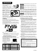
3.1 Mounting
Remove the screw from the front
cover (Fig. 2) and separate the front
cover from the base.
The plastic cap shown is supplied
separately in a small nylon bag -
keep it for later use. Mount the base
equipped with the printed circuit
Figure 2. Cover Assembly
board in the selected location, using the mounting and wiring
knockouts shown in Fig. 1.
Attention! The MCR-100T
includes an additional tamper
switch (under the board) that is
actuated by a leaf spring. A
screw that fastens the tamper
switch actuator to the
mounting surface must be
used, as shown. If the actuator
is secured and the unit is
MCT-100T
Back tamper
switch fixing screw
forcibly removed from its mounting place, the actuator breaks
away from the base, causing the tamper switch opening - a
tamper alarm is consequently transmitted.
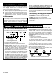
3.2 Wiring
Route the wires through a wiring knockout in the base.
If an input is defined as a Normally Closed (N.C.) type (SW-1 or
SW-2 are set to OFF), series connected normally closed sensor
contacts must be used exclusively.
If an input is defined as an E.O.L. type, Normally Closed (N.C.)
as well as Normally Open (N.O.) sensor contacts can be used. A
47 kΩ resistor must be wired at the far end of the E.O.L. zone
loop, as in Figure 3.
Figure 3. Wiring Example with E.O.L Resistors
Notes:
1. An alarm message will be transmitted once the loop is opened
or short circuited.
2. If you do not need input No. 2, connect it to the GND terminal
with a short length of jumper wire (in case of N.C.) or with a
47 k
Ω
resistor (in case of E.O.L.).
3.3 Setting the Function Selector
Before testing, set DIP switches SW1 through SW4 as required
for the particular application.
The MCT-100 is equipped with
a 4-position DIP switch function
selector (Fig. 4). Each switch
lever allows you to select one
of two options, as explained in
the following table:
Figure 4. Function Selector
Table 1. Getting acquainted with the function selector
Switch Function Pos. Selected Option Default
SW1
IN1 enable/
disable
ON
OFF
Input No. 1 is enabled
Input No. 1 is disabled
ON
SW2
EOL for IN1
and IN2
ON
OFF
Inputs are E.O.L. (47 kΩ)
Inputs are N.C.
OFF
SW3
Restore reports
enable/disable
ON
OFF
Restore events reported
Restore events not reported
ON
SW4
Transmit mode
selector
ON
OFF
Alarms reported every 3 min.
Alarms reported only once
OFF
SWITCH SW1: Determines whether input 1 (IN1) will be enabled
or disabled.
SWITCH SW2
: Determines whether both inputs will behave as
47 kΩ end-of-line (E.O.L.) circuits or as normally closed (N.C.)
inputs.
SWITCH SW3
: Determines whether the transmitter will report
“restore” events.
Note: If the MCT-100 is used in conjunction with motion
detectors, there is no point in setting SW3 to ON, because the
detector restores automatically after an alarm. However, when
the MCT-100 is used with a door or window magnetic switch,
selecting the ON position will enable you to find out whether the
door or window under surveillance are open or closed.
SWITCH SW4
: In non-supervised systems, it is sometimes
required to report an alarm repeatedly at short intervals, until the
disturbed input reverts to its normal (undisturbed) state. Switch
SW4 is used to select between repetitive and one-shot
transmission.
Note: Transmissions initiated by "tamper” events will be repeated
once every 3 minutes, regardless of SW4 setting.
3.4 Battery Insertion and Test
A. Insert the battery between the battery clips, making sure that
the polarity is correct. For proper operation, only Lithium
Thionyl Chloride battery (as specified in Section 2)
should be used.
Note: Before each supervision report, the battery voltage is
tested. If a low battery condition is detected, a "low battery"
alert signal will be included in the supervision message.
If the battery is not replaced, all following transmissions will
include the "low battery" alert signal, which has to be acted
upon without delay.
B. Since the cover is removed and power is applied, a tamper
situation exists. Verify that the MCT-100 transmits (the LED
lights briefly) once every 3 minutes.
C. When you are satisfied that tamper transmissions are carried
out properly, put the cover back on to return the tamper
switch to its normal undisturbed position. Wait slightly over 3
minutes to verify that tamper transmissions cease.
D. Momentarily disturb any one of the sensors connected to the
first input (IN1) and verify that the transmitter LED lights,
indicating that transmission is in progress. IF SW4 is on, wait
3 minutes to verify that the transmission is repeated at 3-
minute intervals.
E. Restore the sensor to the undisturbed state and watch the
LED. If SW3 is set to ON, another transmission will take place
upon restoral.
F. Repeat Steps D and E above with the second input (IN2).
G. Refer to the target receiver's installation instructions, and let
the receiver "learn" the ID codes associated with both inputs
of the MCT-100.
ATTENTION! Because each input of the MCT-100 acts as
an independent transmitter with an individual ID, make sure
that both input IDs are learned by the receiver.
With the target receiver in the LEARN mode, an alarm
transmission from each input will enroll the input’s ID in the
receiver’s memory.
A tamper transmission will also work if you remember this:
- If the Input No. 1 is enabled (SW1 is ON), the tamper
message will be sent with Input 1’s ID.
- If Input No. 1 is disabled (SW1 is OFF), the tamper
message will be sent with Input 2’s ID.
H. Secure the front cover with the screw and screw cap (Fig. 2).