
User's Manual

D-300586 3
4. MISCELLANEOUS COMMENTS
4.1 Product Limitations
Visonic Ltd. wireless systems are very reliable and are tested to
high standards. However, due to low transmitting power and
limited range (required by FCC and other regulating authorities),
there are some limitations to be considered:
A. Receivers may be blocked by radio signals occurring on or near
their operating frequencies, regardless of the digital code used.
B. A receiver can only respond to one transmitted signal at a time.
C. Wireless equipment should be tested regularly to determine
whether there are sources of interference and to protect
against faults.
4.2 Statements
This device complies with Part 15 of the FCC Rules and RSS-
210 of Industry and Science Canada. Operation is subject to the
following two conditions: (1) This device may not cause harmful
interference, and (2) this device must accept any interference
received, including interference that may cause undesired
operation.
The user is cautioned that changes or modifications to the
unit, not expressly approved by Visonic Ltd., could void the
user's FCC or other authority to operate the equipment.
This device complies with the essential requirements and
provisions of Directive 1999/5/EC of the European Parliament and
of the Council of 9 March 1999 on radio and telecommunications
terminal equipment.
4.3 Frequency Allocations for Wireless
Devices in European (EU) Countries
• 433.92 MHz has no restriction in any EU member state.
• 315 MHz is not allowed in any EU member state
• 868.95 MHz (wide band) is allowed in all EU member states.
• 869.2625 MHz (narrow band) are not restricted in any EU
member state.
APPENDIX A. THE VISONIC LTD. POWERCODE SYSTEM
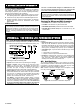
A-1. The PowerCode Message Format
The PowerCode message transmitted by the MCT-100 includes
the 24-bit ID of the input of origin and a status report (see Fig. A1).
Figure A1. Transmitted Data
A message includes the following data:
• Input ID: The 24-bit ID of the input sending the message.
• Tamper / Restore: Upon removal of the unit's front cover,
Input 1 (or input 2 if input 1 is disabled) will send out a
message with a "tamper marker" set to ON. If the unit's cover is
put back, the “input in charge of reporting” will initiate a
message with the tamper marker OFF ("Tamper Restore").
• Alarm / Restore: Once the input loop is disturbed, a message
will be transmitted with an "Alarm marker" ON. Upon restoral of
the input loop, a message will be transmitted with the alarm
marker set to OFF (provided that restore transmission is
desired - SW-3 has been set to ON - see Para. 3.3.).
Low Battery: A special battery condition marker is used to
report the battery status in any message. The battery is tested
once an hour and if found low, Input 1 will initiate a message in
which the "Low Battery” marker is set to ON. This marker will
be ON in all messages that follow, whatever the cause for
transmission. Once the battery is restored to normal,
this
marker will be OFF in all messages that follow (“Battery
Restore”).
• Supervision Report: A special "supervision message” marker,
when set to ON, identifies the periodic supervision messages
transmitted automatically at 60 minute intervals. This marker
will be OFF in all other messages. Supervision messages are
sent by input 1 (if enabled) or by input 2 (if input 1 is disabled).
• Transmitter Type: A special marker indicates the type of the
transmitter:
Supervised or non-supervised
Reports or does not report restorals after alarm
• Checksum: Checksum bits at the end of the message allow
the receiver to determine whether an incoming message is
valid (error-free). This feature considerably upgrades the
reliability of the wireless communication link.
A-2. Anti-Collision
To overcome message collisions at the receiving end, Power-
Code transmitters transmit 3 data bursts at random intervals, with
6 repetitions of the same message in each burst (Fig. A2). This
redundancy improves the probability of reception.
Note: Periodic supervision messages are an exception to this
rule - they consist of a single
6-message burst.
Figure A2. Anti-Collision Transmission Sequence