
Manual
14
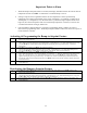
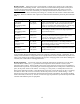
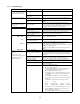
3.5 Timer Controls. The timer section turns the heating outlets either ON or OFF in an unattended
operation when the time in the counter expires. To enter a value into the timer press the up or down
buttons (12) to increase or decrease the displayed time. The format of the display is ‘Hr : Min’. A
simple way to know whether the heating outlets are ON or OFF is by the state of LED 14 which is lit
when the outlets are ON and not lit when they’re OFF. The heating outlets will be ON or OFF depending
on the position of switch 13 as outlined in the table below.
Switch 13 Time Remaining Outlets LED 14
Position on Clock are: is Comment
[When time =
0
turn outlet:]
Zero
OFF
OFF
OFF
>Zero
ON
ON
Heating remains ON until the timer
counts down to zero, at which point the
outlets turn OFF and stay off until reset.
[When time =
0
turn outlet:]
Zero
ON
ON
ON
> Zero
OFF
OFF
Heating remains OFF until the timer
counts down to zero, at which point the
outlets turn ON and stay on indefinitely.
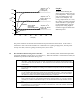
WARNING: A potential danger exists when using the timer to turn heating outlets ON when the
timer counts to zero. During a power failure, the time remaining in the timer is lost. When the power
comes back on the timer resets to zero, which turns outlets ON. Therefore, only processes that pose no
danger when heated indefinitely should be set up to turn on when the timer counts to zero.
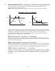
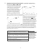
3.6 Temperature Sensor Input. Each controller is fitted with a specific type of temperature sensor input
and can only be used with a temperature sensor of the same type (thermocouple or RTD). For the correct
temperature to be displayed, the thermocouple type must match the receptacle type on the front of the
controller (Figure 1; #7). All thermocouples are color coded to show their type (Blue = type T; Yellow =
type K; Black = type J). The color of the thermocouple plug must match the color of the receptacle on the
front of the controller.
The thermocouple plug on the left is connected to the setpoint controller on the far left and that on the
right to the limit controller. If the thermocouple to either unit becomes broken or disconnected, the
controller displays an error message and stops heating. Rather than using one dual element thermocouple,
2 single element thermocouples can be used if desired.
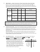
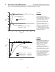
3.7 Power Reduction Circuit. This circuit (11) limits the maximum output power delivered by the
controller. It determines whether the controller heats at a very low
(1-10 mL), low (10 - 100 mL),
intermediate
(50 - 500 mL), medium (300 mL - 2 L), or high (>2 L) power level.
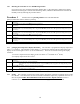
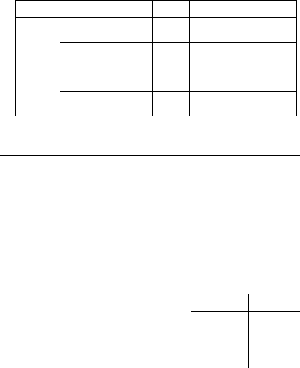
The power reduction circuit acts as a solid state variac. The
table to the right shows the maximum output power from the
controller to the heater depending on the position of the
power switch. A new power setting was added to this circuit
that is not labeled on the front of the cabinet. The new
setting is 1 ‘click’ to the left of the 1-10 ml setting and is
“power off”. In this position the controller doesn’t heat but
acts as a digital thermometer. The correct setting for this
switch is the setting that supplies adequate power for the
heater to heat to the set point in a reasonable period of time
while at the same time not overpowering it.
Front Panel Approx. % of
Volume Range Full Power
[New setting to the left
of the “1-10 ml” setting] 0
1 - 10 mL 3
10 - 100 mL 10
50 - 500 mL 25
300 ml - 2 L 50
≥ 2 L 100