
Manual


9
Section 3: Operations Guide
3.1 Front Panel Description.
S
e
t
p
o
i
n
t
C
o
n
t
r
o
l
l
e
r
L
i
m
i
t
C
o
n
t
r
o
l
l
e
r
1
2
3
4
5
6
7
8
9
10
11
12
14
13
15
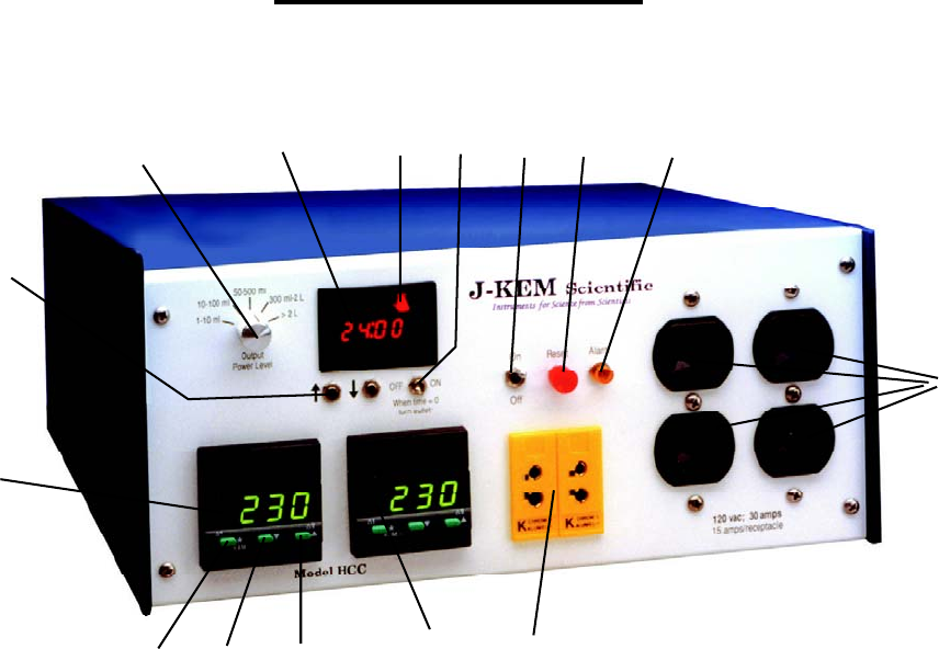
Figure 1
1. Temperature Display. Shows temperature of the process as the default display. Shows set point
temperature (i.e. desired temperature) when ‘
*
’ button is pressed.
2. Control Key. When pressed, the display shows the set point temperature. To decrease or increase
the set point, press the ‘▼’ key (3) or ‘▲’ key (4), while simultaneously depressing the control key.
The set point appears as a blinking number in the display.
3. Lowers set point when ‘
*
’ button (2) is simultaneously pressed.
4. Raises set point when ‘
*
’ button (2) is simultaneously pressed.
5. Limit Controller. This controller sets the temperature that causes the over temperature circuit to
activate disconnecting power from outlets 8 (see Section 3.3).
6. Indicates an over temperature condition and heating has stopped when lit. See Section 3.3.
7. Temperature Sensor Input. Use the same type of sensor probe as the sensor plug installed on the
controller (see Section 3.6). The correct sensor type has the same color plug as the receptacle (7)
on the front of the controller. To operate properly, the receptacle on the left (connected to the
process controller on the left) and the one on the right (connected to the limit controller) must each
have a thermocouple attached.
8. Power Outlets. For Models HCC-130 plug only 120 VAC devices into these outlets. For Models
HCC-215 and HCC-230, plug only 240 VAC devices into these outlets. See Section 3.2.
9. Over Temperature Reset Switch. Press switch to reset the over temperature circuit. The
temperature on the limit controller (5) must be above ambient to reset this circuit.