24-Port 3.5” Mini-SAS Backplane 80H10024001A0 User’s Manual CHENBRO 24-Port 3.5” mini-SAS Backplane with Expander 80H10024001A0 December 2012 15Fl., No.150, Jian Yi Road, Chung Ho City, Taipei Hsien, Taiwan R.O.C., Tel: +886 2 82265500 Fax: +886 2 82265392 e-mail: info@chenbro.com.tw 1 w w w . c h e n b r o .
4-Port 3.5” Mini-SAS Backplane 80H10024001A0 User’s Manual Copyright Copyright © 2012 Chenbro Micom Co., Ltd.. All rights reserved. Unless otherwise indicated, all materials in this manual are copyrighted by Chenbro Micom Co., Ltd.. All rights reserved. No part of this manual, either text or image may be used for any purpose other than internal use within purchasing company.
24-Port 3.5” Mini-SAS Backplane 80H10024001A0 User’s Manual Contents Copyright……………………………………………………….………………………..2 Technical Support……………………………………………….………………………2 Contents………………………………………………………….………………………3 Safety Instruction………………………………………………….…………………….4 Revision History…………………………………………………………………………4 6Gb/s Backplane Specification…………………………………………………………5 Backplane Layout……………………………………………………………………6~11 Fabricate Sequence………………………………………………………………..12~17 w w w . c h e n b r o . c o m 15Fl., No.
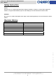
24-Port 3.5” Mini-SAS Backplane 80H10024001A0 User’s Manual Safety Instruction Caution: Informs the user of conditions that might result in damage to hardware, corruption of customer data or application software, or long-term health hazard to people. A caution always precedes the information to which it relates. WARNINGS: Alerts the user to conditions that might result in injury or death. A warning always precedes the information to which it pertains.
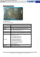
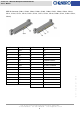
24-Port 3.5” Mini-SAS Backplane 80H10024001A0 User’s Manual 6Gb/s Backplane Specification P/N: 80H10024001A0 HDD BACKPLANE TOP VIEW Specification Hot Interface Mini-SAS HDD Interface SAS Hot-Swap Yes, allows user to replace Hard Disk drive on line Display Cooling LED indicates Hard Disk Drive status Error LED- Red (When HDD is error) Three Fan Connector Environment Monitor Temperature senor detect (RT1, RT2) 1. SAS Connector 29 P*24 2. Mini-SAS Connector*3 3.
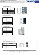
24-Port 3.5” Mini-SAS Backplane 80H10024001A0 User’s Manual Fan Connector (JF1~JF3) Pin NO. Description 1 GND 2 12V 3 FAN Clock Input 4 FAN PWM Output RS232 Connector (JC1) Pin Description NO. 1 GND 2 KEY PIN 3 RXD 4 TXD I2C Connector (JC2) Pin Description NO. 1 SDA 2 GND 3 SCL 4 +5V w w w . c h e n b r o . c o m POWER FAIL ALARM Connector (JP1) Pin Description NO. 1 GND 2 Fall signal Input (Active Low) 15Fl., No.150, Jian Yi Road, Chung Ho City, Taipei Hsien, Taiwan R.
24-Port 3.5” Mini-SAS Backplane 80H10024001A0 User’s Manual POWER FAIL MUTE Connector (JM1) Pin Description NO. 1 MUTE- 2 MUTE+ 2.54 Pin Header (JC4) Pin Descriptions Pin NO. Descriptions 1 FAIL LED+ 2 FAIL LED- 3 KEY PIN 4 NC 5 MUTE SW+ 6 MUTE SW- Descriptions Pin NO. Descriptions 1 GND 5 12V 2 GND 6 12V 3 GND 7 12V 4 GND 8 12V NO. ATX 8P Connector (CN1) Pin NO. w w w . c h e n b r o . c o m ATX 4P Connector (CN2~CN3) Pin Descriptions Pin NO.
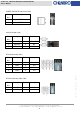
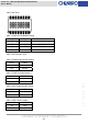
24-Port 3.5” Mini-SAS Backplane 80H10024001A0 User’s Manual MINI SAS CONNECTOR (CB1~CB3) 正視圖 Pin NO. Descriptions Pin NO. Descriptions GND B1 GND A2 RP1 B2 TP1 A3 RN1 B3 TN1 A4 GND B4 GND A5 RP2 B5 TP2 A6 RN2 B6 TN2 A7 GND B7 GND A8 NC B8 NC A9 NC B9 NC A10 NC B10 NC A11 NC B11 NC A12 GND B12 GND A13 RP3 B13 TP3 A14 RN3 B14 TN3 A15 GND B15 GND A16 RP4 B16 TP4 A17 RN4 B17 TN4 A18 GND B18 GND w w w . c h e n b r o . c o m A1 15Fl.
24-Port 3.5” Mini-SAS Backplane 80H10024001A0 User’s Manual HDD IN Connector (CH011, CH021, CH031, CH041, CH051, CH061, CH071, CH081, CH091, CH101, CH111, CH121, CH131, CH141, CH151, CH161, CH171, CH181, CH191, CH201, CH211, CH221. CH231, CH241) Descriptions Pin NO.
24-Port 3.5” Mini-SAS Backplane 80H10024001A0 User’s Manual SW1 FUNCTION SW1-1 & SW1-2: FAN Number Setting SW1-1 SW1-2 FAN OFF OFF ALL FAN OFF (Default) OFF ON FAN1 ON ON OFF FAN1,2 ON ON ON FAN1,2,3 ON SW1-3: NC (Default is OFF) SW1-4: PWM Enable/ Disable Setting SW1-4 PWM ON Enable (Default) OFF Disable SW1-5: TEMP Threshold Setting SW1-5 TEMP ON 65℃ (Default) OFF 55℃ w w w . c h e n b r o .
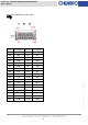
24-Port 3.5” Mini-SAS Backplane 80H10024001A0 User’s Manual SW1-8: CB3 Function Setting SW1-8 CB3 ON HDD OFF Daisy Chain (Default) w w w . c h e n b r o . c o m 15Fl., No.150, Jian Yi Road, Chung Ho City, Taipei Hsien, Taiwan R.O.C., Tel: +886 2 82265500 Fax: +886 2 82265392 e-mail: info@chenbro.com.
24-Port 3.5” Mini-SAS Backplane 80H10024001A0 User’s Manual HDD 1 HDD 9 HDD 17 CONNECTOR HDD 2 HDD 10 HDD 18 HDD 3 HDD 11 HDD 19 HDD 4 HDD 12 HDD 20 HDD 5 HDD 13 HDD 21 SIDE HDD 6 HDD 14 HDD 22 HDD 7 HDD 15 HDD 23 HDD 8 HDD 16 HDD 24 HDD NO.
24-Port 3.5” Mini-SAS Backplane 80H10024001A0 User’s Manual HDD BACKPLANE BACK SIDE WITH EXPANDER & HEATSINK STEPS TO INSTALL HDD BACKPLANE: 1. Tear up the thermal paste sticker of heatsink on HDD backplane backside, before installing on metal tray. 2. To install transparent insulator above HDD backplane on metal tray by 12pcs screws. w w w . c h e n b r o . c o m 15Fl., No.150, Jian Yi Road, Chung Ho City, Taipei Hsien, Taiwan R.O.C., Tel: +886 2 82265500 Fax: +886 2 82265392 e-mail: info@chenbro.com.
24-Port 3.5” Mini-SAS Backplane 80H10024001A0 User’s Manual 3. Slide in metal tray into chassis, then connect all cables before push metal tray to the end. 4. Connect all cables: CAUTION: DIP switch default set-up are different for HDD BP 1 and BP 2. Fan Fan 2 Fan 3 HDD BP HDD BP 2 Note: Connector JF1, JF2, JF3 are DIP (2) PSU 2pin mute cable connects to JM1, 2pin switch adjustable alarm cable connect to JP1 (3) Chassis front Fan 1 and Fan 2 connect to HDD BP 1, and Fan 3 connects to HDD BP2 15Fl.
24-Port 3.5” Mini-SAS Backplane 80H10024001A0 User’s Manual Connect power supply 12V ATX 8P cable to HDD WARNING: BP connector CN1, 2pcs 5V ATX 4P cable to Power connectors are different from CPU connector CN2, CN3 4pin/8pin connector. CB1 CB2 CB3 Mini SAS connector (left to right) z CB1_Mini SAS IN z CB2_Mini SAS IN/OUT (switchable) z CB3_Mini SAS OUT NOTE: CB2, CB3 are DIP Switch adjustable w w w . c h e n b r o . c o m 15Fl., No.150, Jian Yi Road, Chung Ho City, Taipei Hsien, Taiwan R.
24-Port 3.5” Mini-SAS Backplane 80H10024001A0 User’s Manual HDD BP 1 connects with Fan 1, Fan 2, DIP switch default set-up is No. 2, 3,5 OFF, No. 1, 4, 6, 7, 8 are ON. HDD BP 2 connects with Fan 3, DIP switch default set-up is No.1, 3, 5 OFF, No. 2, 4, 6, 7, 8 are ON. 5. Push metal tray in place then tighten two thumb screws with chassis. w w w . c h e n b r o . c o m 15Fl., No.150, Jian Yi Road, Chung Ho City, Taipei Hsien, Taiwan R.O.C., Tel: +886 2 82265500 Fax: +886 2 82265392 e-mail: info@chenbro.
24-Port 3.5” Mini-SAS Backplane 80H10024001A0 User’s Manual STEPS TO MAINTAIN HDD BACKPLANE: 1. Power off system 2. Remove all HDDs and holders 3. Release thumb screws and slightly pull out BP 4. Disassemble all cables from BP end connectors 5. Slide out metal tray completely w w w . c h e n b r o . c o m 15Fl., No.150, Jian Yi Road, Chung Ho City, Taipei Hsien, Taiwan R.O.C., Tel: +886 2 82265500 Fax: +886 2 82265392 e-mail: info@chenbro.com.