RM312 Rackmount Chassis User Guide Rev.
Contents YOUR RACKMOUNT CHASSIS........................................................................1 FEATURES .......................................................................................................1 SPECIFICATIONS ...............................................................................................2 LAYOUT ..........................................................................................................3 INSTALLATION .....................................................
YOUR RACKMOUNT CHASSIS The RM312 19" rackmount chassis supports a variety of high-density system configurations and features the latest in server-chassis technology. Features Top Cover Ø Screw-less design for easy installation and maintenance Ø Quick reference guide affixed to the inside Front Ø Ø Ø Ø Panel Controls and Indicators Front access USB2.
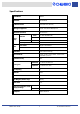
Specifications Model Name RM312 Standard EIA-RS310D M/B Form Factor Extended ATX (12"x13") CPU Type Supported P4/DP Xeon/Athlon MP/Opteron Dimension (D*W*H) 660*430*176mm 26*16.9*5.2" External Drive Bays PSU Internal 5.25” 1 x slim CD/DVD-ROM 3.5” 1 x FDD 3.5” 1 HDD Trays 12 Form Factor Single or Redundant Watts 350W ~ 800W Indicators Power On/Off, HDD/LAN activity, fan failure, and overheat warning Front Controls Power On/Off, System Reset, Alarm Reset, and USB2.
Layout Chassis Two 60mm Exhaust Fans (optional) Standard ATX/ Extended ATX M/B Single or n+1 Redundant Power Supply (optional) 4x 80mm Easy Swap Fan Modules Slim CD-ROM Internal 3.5" Hard Drive Standard FDD or Internal HDD 12x Hard Drive Trays See Front Panel Inset for details Front Access Panel Front Panel Inset A A. B. C. D. E. B C HDD Tray Activity LEDs (1-12) USB2.0 Port x2 LAN1 and LAN2 LEDs Alarm Mute Button System Reset Button RM312 User Guide D E F G H F. G. H. I.
Back Panel Two 60mm Exhaust Fans (optional) Single or n+1 Redundant Power Supply (optional) RM312 User Guide System I/O Ports (M/B dependent) 4 Seven PCI Slots 19" Rackmount Chassis
INSTALLATION For your safety When deciding on a location for your RM312 rackmount chassis, please take the following into consideration: Electric Power: The power cord is what powers on/off your chassis, so try to place the chassis near a power outlet for convenience. Next, be aware of RM312's power rating to avoid overloading its circuits. Then make sure the connections are grounded properly. Temperature: Whenever dealing with an enclosed environment, temperature must be a consideration.
Parts List • RM312 Rackmount Chassis (P/N: 90-331200-001) • Accessory Box (P/N: 84-331210-001) - CD-ROM Adapter (P/N: 80-091801-011) - Screws and Spacers: DEVICE PACKET PART NO.
- Cables: (refer to Appendix A for further cable options) CABLE PART NO.
Installing Hard Disk Drives (HDD) ? ? ? 1. Press latch towards the right to open the lever release and slide the HDD tray out of the chassis. 2. Mount the hard drive onto the tray with four screws from the HDD screw packet (P/N: 70-000000-149). 3. Slide the HDD tray back into the case and press the lever back in to secure it. 4. Repeat the procedure for the remaining hard drives. Installing an Internal HDD ( STANDARD ) ( OPTION ) ? ? ? ? 1.
Installing a FDD ? ? ? 1. Remove the securing screw to move back and take out the bracket. 2. Remove the bracket's FDD cover screws. 3. Attach the FDD onto the bracket with four additional screws from the included FDD screw packet (P/N: 70-331900-101). 4. Slide the bracket forward, following the three guide pins, until it fits into place. 5. Reattach the original securing screw. Installing a Slim CD/DVD-ROM ? ? ? 1. Release the securing screw to slide back and take out the bracket. 2.
Changing the 80mm System Fans Ž • • 1. 2. 3. 4. 5. 6. Disconnect the fan connector from the backplane. Push the press tab down, then ease the fan and its frame out of the fan bracket. Pull the press tab up to release the fan from the frame. Remove the four screws to take out the finger guard. Replace the faulty fan with a new one. Reassemble, then place back into the fan bracket and reconnect to the backplane.
Installing the Backplane (optional item) RM312 supports the following three different backplanes: SCSI, IDE, and SATA.
? ? ? ? 1. With ten screws from the backplane screw packet (P/N: 70-331900-102), attach the backplane to the bracket in the chassis as shown in the diagram. 2. To support a second backplane, affix three hex copper spacer pins. 3. Next secure both ends of the backplane with two screws on both sides of the outer chassis. 4. Repeat steps 1-3 for remaining backplane assemblies. 5. For the topmost assembly, use the three hex copper spacers without the pins to cap it off. 6.
Installing a Motherboard (optional part) ? ? ? ? ? 1. Use the included spacers for support from the motherboard screw packet (P/N: 70-331100-101). 2. Install the I/O gasket that came with your motherboard (M/B). 3. Next align the M/B with the chassis and I/O gasket. 4. The edge with the I/O ports should be placed at the back part of the chassis. 5. Secure M/B to the chassis with a screw. Installing the Power Supply Unit (optional device) ? ? 1.
Installing the General Rack Rail Kit (optional part) Sliding Rail Guide (inside facing chassis) Outer Fixed Rack Rail Screws Inner Fixed Chassis Rail The optional rack rail kit consists of three main parts: a pair of inner fixed chassis rails, a pair of outer fixed rack rails, and a pair of sliding rail guides. Each pair is identical, so no special attention is necessary to make the parts match either the left or the right side.
Installing the Bezel ? ? ? 1. First detach the handles by removing the two screws from each one. Keep handles in the event you may need them again in the future. 2. Next, install the bezel supports and tighten screws securely. 3. Then fit the right side of bezel to its corresponding support and snap into place.
BACKPLANE BOARD Raid Backplane Supports: Ø Ø Ø Ø Ø Ø Ø Ø Ø Ø Ø Ø Ø SCSI interface: Ultra 320/160 backward compatibility Hard disk drive 80pin SCA2 Ultra 320/160 backward compatibility 4-bay hard disk drive inrush current control for hot-swapping SCSI-IN and SCSI-OUT connector (right angle, 68-pin female) SCSI on board terminator On/Off function and On/Off LED Hard disk drive Delay_Start or Remote_Start mode function SCA2 ID setting function default is ID0, ID1, ID2, ID3 5pcs external fan speed monitoring,
Backplane Layout Dimensions: 411.60*51.44*2.
Connectors and Switches No. J1 J2 J3 J4 J5 J6 J7 J8 JP1 S1 S2 Description HDD1 SCA2 Connector HDD2 SCA2 Connector HDD3 SCA2 Connector HDD4 SCA2 Connector SCSI in 68pin Connector SCSI in 68pin Connector DC Power Input for Big 4P DC Power Input for Big 4P For LED Output Header Function Set Switch HDD1 ID-Set Switch No.
S1: Function Settings* Switch Switch On Switch Off Switch 1 HDD motor spin up delay mode Normal Switch 2 HDD motor spin up remote mode Normal Switch 3 Terminator On Terminator Off * With this jumper, the user can set the SCSI HDD motor to start in sequence or randomly.
LED BOARD Features Ø Ø Ø Ø Ø Ø Ø Ø Ø Ø Ø Ø Ø PCB Layers: 2 1 HDD power and access LED monitor 1 buzzer alarm mute switch 1 system reset switch 1 system power switch 1 power green LED indicator 1 local HDD yellow LED indicator 1 fails red LED indicator 2 USB port 2 LAN LED indicator 4 connectors for 1U, 2U, 3U, 4U LED boards 2 x 10 pin connectors for USB port 1 system connector RM312 User Guide 20 19" Rackmount Chassis
LED Board Layout SW3 J5 LED6-3 LED6-2 LED6-1 J4 J2 SW2 J3 SW1 J1 LED5 USB。ム2 LED4 LED3 LED2 LED1 USB Connector Dimensions: 130.0*45.0*1.6mm Connectors and Switches NO. J1 J2 J3 J4 J5 SW1 SW2 SW3 RM312 User Guide Description 1U LED 2U LED 3U LED 4U LED System Alarm Mute SW System Reset SW Power SW NO.
Pin Assignments USB Pin Outs Pin # 1 3 5 7 9 Description USB1 USB1 USB1 USB1 Key Power Data Data + GND Pin # 2 4 6 8 10 Description USB2 Power USB Data USB2 Data + USB2 GND None J1: 1U LED Board Pin Outs Pin # 1 3 5 7 9 11 13 Description LED11 + LED12 + LED13 + LED14 + +5V VCC Mute None Pin # 2 4 6 8 10 12 14 Description GND GND GND GND Fail GND Key J2: 2U LED Board Pin Outs Pin # 1 3 5 7 9 11 13 Description LED21 + LED22 + LED23 + LED24 + +5V VCC Mute None Pin # 2 4 6 8 10 12 14 Description GND
J4: 4U LED Board Pin Outs Pin # 1 3 5 7 9 11 13 Description LED41 + LED42 + LED43 + LED44 + +5V VCC Mute None Pin # 2 4 6 8 10 12 14 Description GND GND GND GND Fail GND Key J5: System Pin Outs Pin # 1 3 5 7 9 11 Description Reset Power Switch Power LED + HDD LED + LAN1 LED + LAN2 LED + RM312 User Guide Pin # 2 4 6 8 10 12 Description Reset GND Power Switch GND Power LED HDD LED LAN2 LED LAN2 LED - 23 19" Rackmount Chassis
APPENDIX A Optional Cables USB: TYPE LENGTH PART NO. Intel Spec 750mm 26-033219-001 Universal Spec 750mm 26-033219-002 CABLE A PPEARANCE IDE: TYPE LENGTH PART NO. ATA-133 IDE 700mm 26-073215-001 ATA-133 IDE 560mm 26-073118-006 CABLE A PPEARANCE SATA: TYPE LENGTH PART NO.
APPENDIX B Power Cord Plug Options COUNTRY/REGION PART NO.
NOTICES © 2003 Chenbro Micom Co., Ltd. All rights reserved Chenbro Micom Co., Ltd. reserves the right to make improvements to the products described in this manual at any time. Specifications and features are subject to change without prior notice. No part of this manual may be reproduced, copied, translated, or transmitted in any form or by any means without the prior written permission of Chenbro Micom Co., Ltd. Information provided in this manual is intended to be accurate and reliable.
CONTACT INFORMATION Headquarters CHENBRO MICOM CO., LTD. 150 Jian Yi Road, 15F Chung Ho City 235, Taipei County Taiwan Tel: +886 (2) 8226-5500 Fax: +886 (2) 8226-5423 E-mail: info@chenbro.com.tw Website: www.chenbro.com.tw CHENBRO MICOM (USA) INC. 2260 S. Haven Ave., Unit E Ontario, CA 91761 USA Tel: 1-909-947-3200 Fax:1-909-947-4300 E-mail: info@chenbro.com CHENBRO UK 8 Ledbury Avenue, Davyhulme Manchester, M41 7AL UK Tel: +44 (161) 749-9015 Fax: +44 (161) 749-9219 E-mail: franceslu63@btinternet.